Some Theory
The basic operation principle of a stepper motor is not much different from a DC or AC motor: they are formed by coils and magnets with a moving shaft that moves when power is applied. The difference is in the way the shaft is moved: they move the rotor by applying power to diferent coils in a determinated sequence (stepped). The steppers are previewed for fine control requirements and will not only spin on comand, but also at any number of steps per second, up to a maximum speed. Another function not performed by common motors is that the stepper motors can hold teir position and resist turning.
Figure 1 shows the symbol adopted to represent a stepper motor and the aspect of the most commun types.
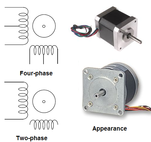
The robot and mechatronic designer don't need to buy expensive stepper motors for their projects since many of them can be found in good operation condictions in diskette drivers of computers, printers and many other devices out of use.
How it works
A stepper motor converts digital information into proportional mechanical movement. They are different from the DC motors that can be controlled by changing the current accross them. Stepper motors are digital.
Stepper motors can be found in three basic types: permament magnet, variable reluctance and hybrid.
The way the windings and are organized inside a motor determine how they work. The most common type is the four phase stepper motor but there are also two phase and six phase types.
Figure 2 shows the more popular of the stepper motors: the four phase stepper motor.
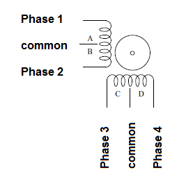
Inside this motor we find four windings. Since each pair of windings have a common connection, this kind of motor can be easily identified by the six wires for connections.
In the normal operation, the common wires are connected to the positive trail of the power supply and the other wires are put to ground for a short period of time as long you want to energize the correspondent winding.
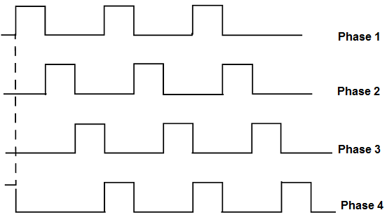
Each time the motor is energized the motor shaft advances a fraction of revolution. For the shaft turns properly the widnings must be energized by a sequence of pulses or waves.
For instance, if you energize the widings A, B, C and D in this sequence, the shaft turns clockwise. In the other hand, reversing the sequence, the motor turns anticlockwise.
Figure 3 shows the sequence that is normally used to energize four-phase stepper motors.
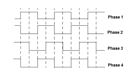
Another way to energize a stepper motor is applying an on-on/off-off sequence. This sequence is shown by figure 4 and have as advantage to increase the driving power of the motor and provide greater shaft rotation precision.
Other common type of stepper motor is the two phase, shown by figure 5.
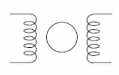
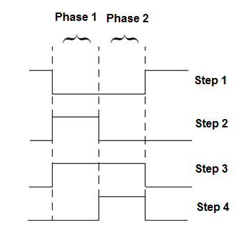
This stepper motor is formed by two coils, as shown by the figure and so can be easily identified by its four wires. This type of motor is energized using a different sequence where the direction of the current accross each winding is considered, as shown by figure 6. In some types the -V can be replaced by the ground.
There are also stepper motors with more phases, as the six-phase stepper motor, but they are not very common. Motors with more phases are more accurate but also more expensive.
For our purposes, with many applications in projects involving robotics and mechatronics, the four-phase stepper motor is the recommended and more part of our blocks in this part is designed for this type of motor.
How to use stepper motors
As we had seen, the windings of a stepper motor must be energized properly to a correct operation. This means that, when using a stepper motor you'll need to know not only electric specifications of this kind of device but also mechanical specifications.
The next are the most important:
Voltage and current
Stepper motors have voltage rated for 5, 6 and 12 volts in more part of the types. Unlike the DC motors is not recommended to overdrive the windings of a stepper motor. Over voltages of more than 30% of the rated voltage can burn the windings.
The current ratings depend on the application (size and torque). The common types can drain currents in the range from 50 mA to more than 1 A. The higher is the current and voltage the higher is the torque.
When designing a power supply for an application using a stepper motor is important to consider that the current ratings are given per winding. So, the power supply must be able to supply at least two times the current for winding or 8 times the current per winding in a four-phase type.
Sequence
Altough more part of the stepper motors uses one of the two sequences shown in the theory, it is possible to find units that are different. When using that units is important to know the sequence of pulses for their correct operation.
Step Angle
When a pulse of the sequence is applied to the motor it advances one step. This means that the shaft moves of a determinated angle. This angle can vary from type to typein the range between 0.8 degrees and 90 degrees.
In a 90 degrees stepper motor, 4 pulses make the shaft to complete one turn as show by figure 7.
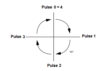
But, it is more common to find stepper motors with step angles of 1.8 degres. This means that you have to apply 200 pulses to the control circuit to make it complete a turn.
Pulse rate
The pulse rate determines the speed of the motor. If you are using a 1.8 degrees step angle motor, and you apply 200 pulses per second, this motor will run at 1 rotation per second or 60 rotations per minute (60 rpm).
Given the step angle it is easy to calculate the rpm:
The stepper motors are devices not intend to high speed applications. The top speed recommended ar in the range of 2 or 3 turns per second or in the range of 120 to 180 rpm.
It is important to remember that in this kind of motor, the torque falls when the speed rises.
Torque
The torque of a stepper motor is not high. A typical stepper motor can only provide about some grams/cm when runing. This means that in applications where high torque is needed, gearboxes must be added.
Since the torque falls with the speed, when using this kind of motor is important that they are used in low speed modes. See part 2 to informations about how to measure the torque.
Braking effect
When keeping the current in a winding after a pulse is applied, the stepper motor can't continue to turn. The shaft is locked as if you have applied brakes.
A circuit that keeps the current in a winding in a determinated position can be used as an electronic brake for a stepper motor.
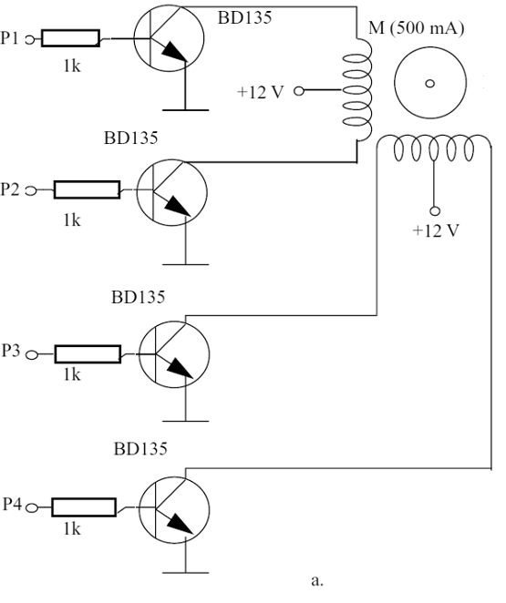
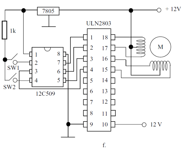
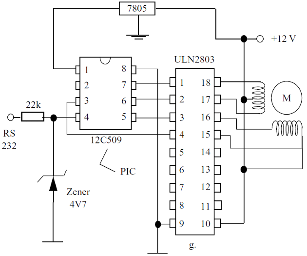
Figure 8 shows some circuits used to control stepper motors:
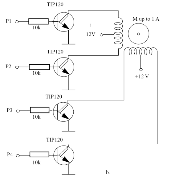
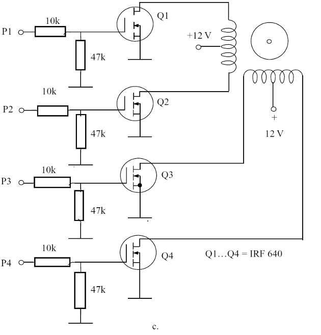
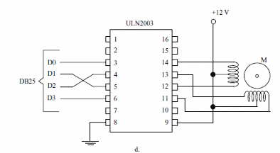
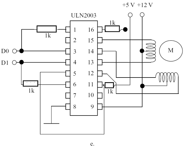
ICs Recommended For Stepper Motors Driving
The next table gives information about other transistor arrays or power stages that are recommended for stepper motor driving.
| Type | Current | Number of Stages | Manufacturer | Observations |
| ULN2003 | 500 mA 7 | 16 pins | ||
| ULN2803 | 500 mA 7 | Equivalent to the UCN2003 but in 18 pin package | ||
| MC1413 | 500 mA 7 | Motorola | TTL compatible | |
| MC1414 | 500 mA 7 | Motorola | CMOS compatible | |
| SN75465 | 500 mA 7 | Texas | 1050 ohms series resistor at each input - TTL compatible | |
| SN75466 | 500 mA 7 | Texas | 2700 ohms series resistor at each input - CMOS compatible | |
| SN75468 | 500 mA 7 | Texas | Indicated for CMOS and TTL with 5 V supply | |
| SN75469 | 500 mA 7 | Texas | 10,500 ohms series resistor at each input - CMOS with 6 to 15 V supplies |


