Programming is a word that means making a plan or planning something that you want or wish to do. This word is common to all microcontrollers, microprocessors, DSPs, etc. Any equipment that has a potential to processinstructions can be programmed.
Instructions, is another key word within the schedule. Let's assume an example and imagine that we have a programmable car, when we can say: start, turn right 20 degrees, then go straight for 3 meters and finally turn left 15 degrees, advance 2 meters and stop. We can see in our example that the programmable car executes instructions like: turn on, turn right, turn left, stop. This is programming. Using instructions to do something.
A car, as we understand it, is a vehicle that can be moved from one side to another. Therefore, its programming is very deductive or intuitive. A microcontroller is very similar to a programmable car, except that it performs other classes of instructions. The instructions that a microcontroller can perform are: to add, subtract, divide, multiply, compare, move a data from one place to another, etc. The complete list of instructions which each microcontroller can perform is listed on its technical sheets.
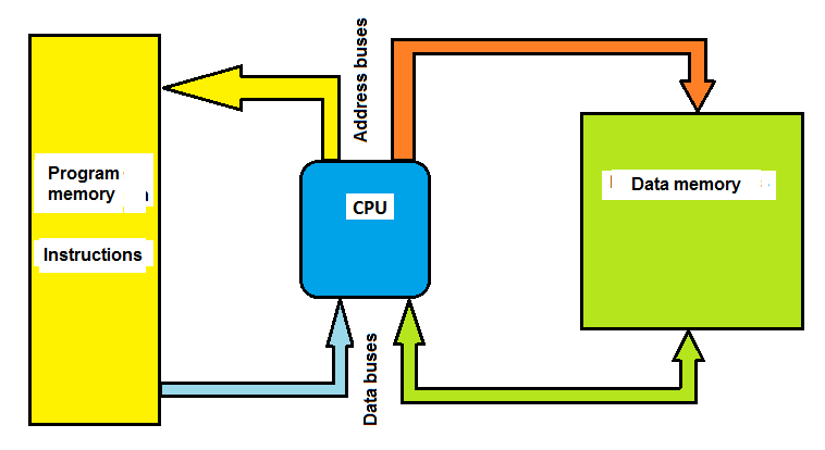
Executing is another key word in microcontroller programming. The instructions within a microcontroller are executed by the central processing unit or CPU. Some instructions come with data or variables. In Figure 1 we can see a block diagram of a basic microcontroller. The program memory stores the instructions. The CPU executes the instructions and stores the data or variables in RAM memory. Here we start an adventure in the programming world of ARM microcontrollers, because the idea is to understand what they have or what they are composed of, what they can do and thus be able to program them.
Classification of ARM Processors
ARM processors can be classified according to the instructions they can perform and their possible applications, being divided into 3 large groups. Figure 2 shows this classification.
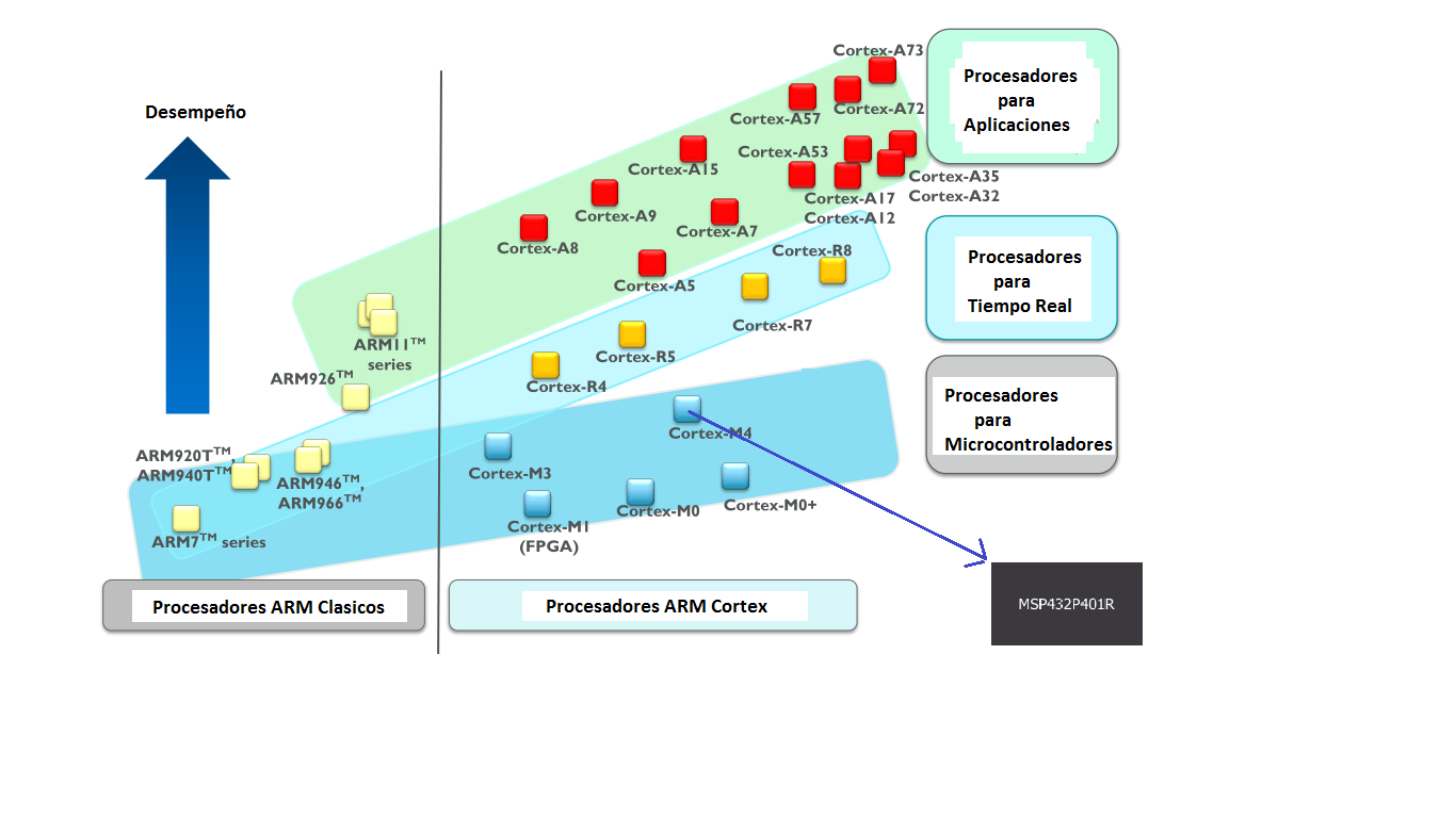
Cortex-A - Processors for applications: they are used in electronic devices or devices where an operating system (OS) such as Linux, Windows, mobile and mobile operating system (Android, Windows Mobile, etc.) is required, which makes these processors appropriate for use on computers, servers, mobile phones, tablets, etc.
Cortex-R - Real-Time Processors: They are used in equipment which must perform instructions in the least possible time, such as vehicle control, brake control for automobiles, robots, airplanes, surveillance and photographic cameras, computer peripherals, etc. .
Cortex-M - Processors for Microcontrollers: are used in home appliances, measurement equipment, industrial control electronics, games, etc.
The Cortex-M processors can still be divided into other categories and instructions which can be executed, as shown in Figure 3.
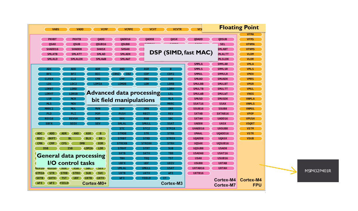
Cortex-M0 and Cortex-M0+: are processors of very low consumption and low cost;
Cortex-M1: A small processor optimized for FPGA (Field Programmable Gate Array).
Cortex-M3: a low-power processor with a rich set of instructions, cumulative divisions and multiplication and ability to debug and trace.
Cortex-M4: with instructions for DPS tasks, faster cumulative multiplications, and ability to debug and trace.
Cortex-M4F: with the same capabilities of the Cortex-M4, plus a unit for arithmetic of simple-precision floating-point.
We can see in Figure 2 and Figure 3 that the MSP432P401 microcontroller belongs to the Cortex-M4F family, that is, one of the best in the Cortex-M family (microcontrollers).
The MSP432P401 Microcontroller
The MSP430P401 microcontroller has the following features and among the many applications in which this microcontroller can be used we can mention:
Flowmeters.
Electrical meters.
Home automation.
Industrial automation.
Smart thermostats.
Access Dashboards.
Gas monitors.
Communication modules.
Clocks.
Digital wireless meters.
Portable medical devices.
Glucose Meters.
Portable devices.
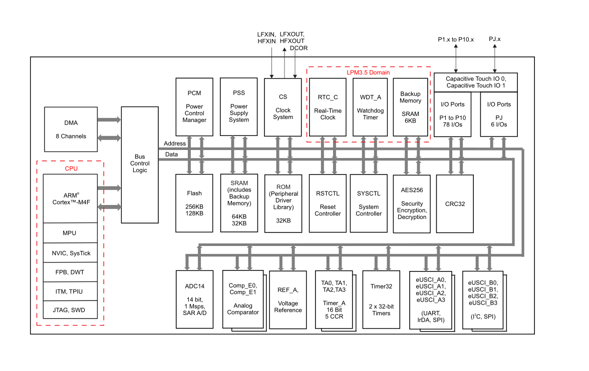
Figure 4 shows the block diagram of the MSP432P401 microcontroller. We can see the CPU Cortex-M4F, flash memory, RAM, ROM, GPIO, ADC, analog comparators, timers, UARTs, SPI, I2C, etc.
The ARM microcontrollers, for better performance, use multiple buses to interconnect their memories and peripherals, but in the diagram of Figure 4, they were omitted for ease of understanding. Thanks to the functions and libraries that Texas Instruments has developed and delivered to the programmer in a software development kit (SDK) called Simple Link, these buses are transparent at the time of programming.
Development Board
Texas Instruments has created an easy-to-use development kit called the MSP-EXP432P401R LaunchPad. With this kit we can begin to program the MSP432P401 and test its multiple peripherals and capabilities.
Figure 5 shows an image of this kit. It should be noted that there are 2 MSP-EXP432P401R kits, called Ver 1.0 (Black) and Ver. 2.0 (Red). The difference between these two versions is mainly aesthetic and to improve their use by the programmer or user. The one shown in Figure 5 is Ver 2.0.
Many development tools or IDE (Editors and Compilers) are available to program the kit such as: Code Composer Studio IDE, IAR Embedded Workbench IDE, Leil uVision IDE.
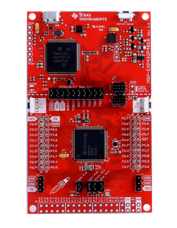
Figure 6 shows a block diagram of the MSP-EXP432P401R kit.
We can observe in this diagram that an external crystal of 48 MHz is used, 40 pins for connection, buttons and LEDs to interact with the user, a JTAG interface for debug purposes, a USB connector to connect to the computer.
Figures 7 and 8 show how to pin the development board. We can observe the various analog inputs, GPIOs, UART, SPI, I2C, PWM, Timers, Capture inputs, etc. The way to pin is a standard compatible with a number of modules designed for this type of board. It is important to be aware and check if the module is 100% compatible or if any modifications are to be made.
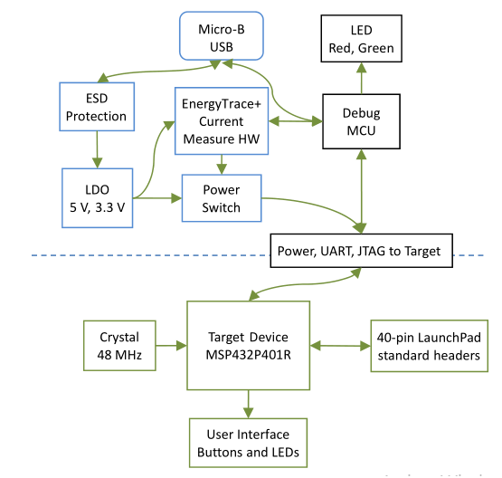
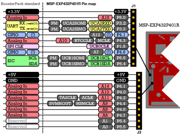
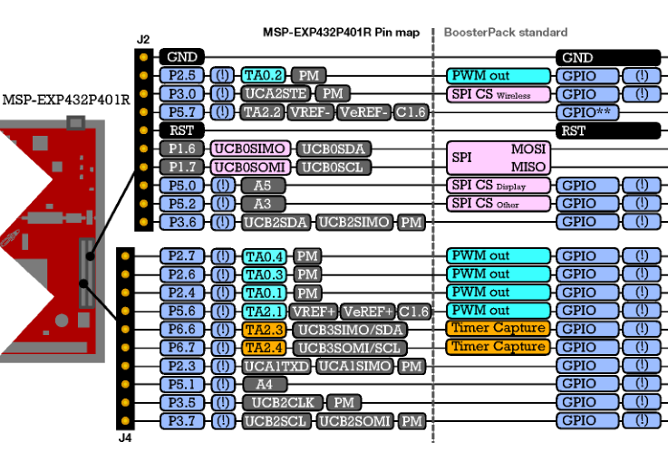
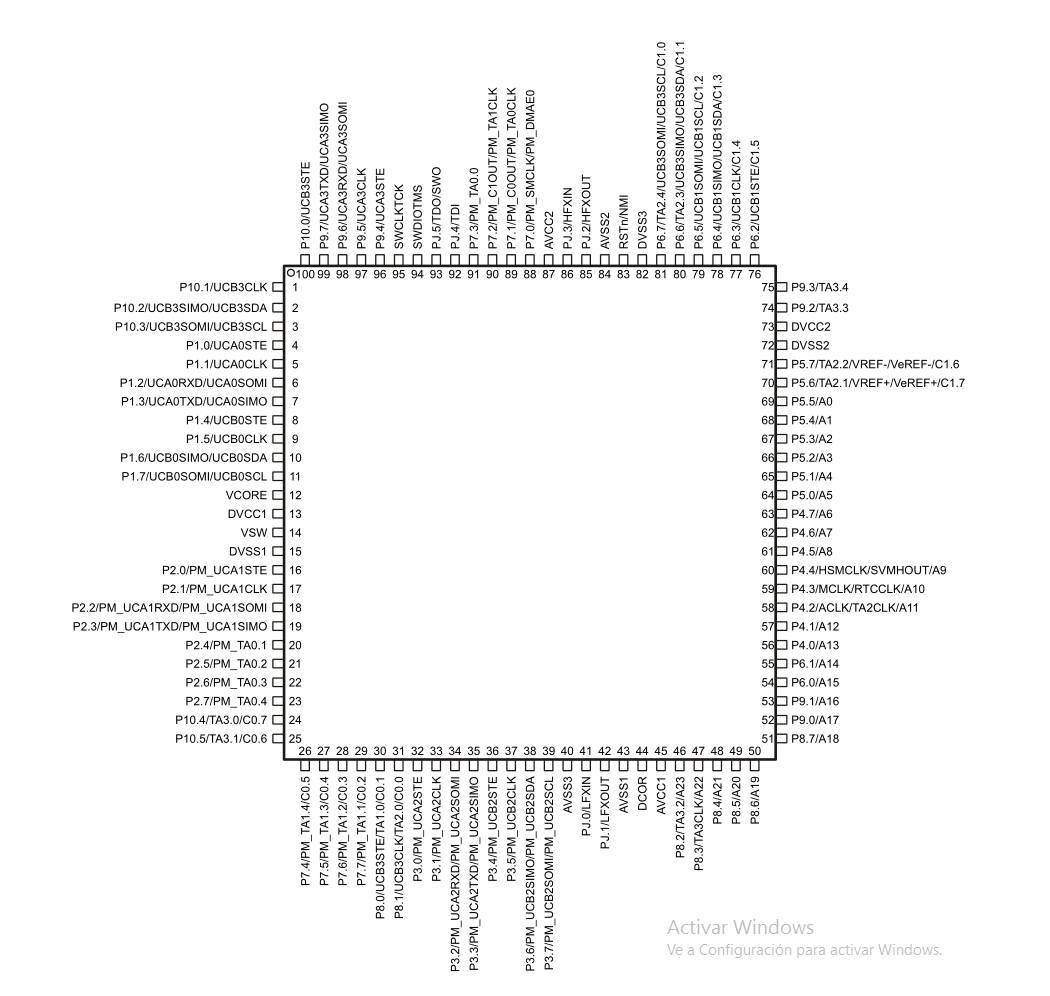
Figure 9 shows the pin assignment of the MSP432P401RIPZ microcontroller where we can observe its rich set of peripherals which has already been indicated.
Programming Tools
Texas Instruments has developed a Software Development Kit (SDK) to facilitate the use and programming of the microcontroller. Figure 10 shows the components wich make the SDK:
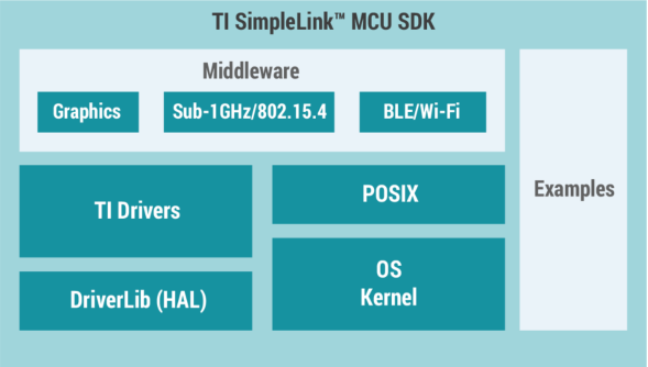
OS / Kernel: is a real-time operating system (ROS) very useful for simplifying the programming task.
POSIX: Application Programming Interface (API) to enable application code to be portable and have compatibility with other OS / Kernels.
DriveLib: is a library (HAL - Hardware Abstraction Layer) which creates a layer between the lowest access of the peripherals and the application.
IT Drivers: they are functions (API) which allow to access the peripherals in a easy way.
Graphics: a library for handling displays (LCDs) and images.
BLE / WiFi: Library for Bluetooth and WiFi connections.
Sub-1 GHz: Library for Sub-1 GHz connections.
Examples: Sample code to demonstrate the use of previous libraries.
To all these functions or routines (SDK), Texas Instruments gave the name SimpleLink. With practice, we will see it is easy to use and its usefulness, since the programmer does not have to worry about the creation of routines to control the peripherals. Thus, the programmer can focus on the application and gain time to finish the project.
EXAMPLE PROGRAM.
One of the most used example programs for microcontroller is to turn on and off an LED (Blinking). In the libraries (SDK) of the MSP432P401 microcontroller, we also find this example to turn an LED on and off.
int main(void)
{
volatile uint32_t i;
// Stop watchdog timer
WDT_A_hold(WDT_A_BASE);
// Set P1.0 to output direction
GPIO_setAsOutputPin(
GPIO_PORT_P1,
GPIO_PIN0
);
while(1)
{
// Toggle P1.0 output
GPIO_toggleOutputOnPin(
GPIO_PORT_P1,
GPIO_PIN0
);
// Delay
for(i=100000; i>0; i--);
}
}
Explaining the program, we can say that the first function that the program calls is main(). The following is a line of code that declares a variable called i:
volatile uint32_t i;
The following line of code is for the watchdog timer:
WDT_A_hold(WDT_A_BASE);
Then we have a line that configures pin 0, from port P1 as output .:
GPIO_setAsOutputPin(
GPIO_PORT_P1,
GPIO_PIN0
);
The following line of code is used for the program to always repeat itself, ie it is an infinite loop :
while(1)
We then have a line of code that is used to measure the status (toggle) of pin 0 from port P1:
GPIO_toggleOutputOnPin(
GPIO_PORT_P1,
GPIO_PIN0
);
The following line of code is used to delay the program for a while so that we can observe the LED blinks:
for(i=100000; i>0; i--);
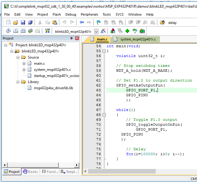
To compile and edit the previous example we used the Keil IDE. Figure 11 shows this development environment.
Another advantage of using the MSP432P401 microcontrollers is their compatibility with the Arduino programming model. Texas Instruments offers a development IDE called Power, which is very similar to Arduino IDE. Figure 12 shows the working environment for the MSP-EXP432P401R board. It is necessary to install the board in the IDE, and to do this go to the menu of tools> board> board manager. The following is an example to turn an LED on and off using the Power IDE:
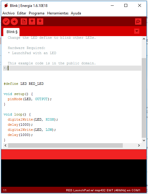
#define LED RED_LED
void setup() {
pinMode(LED, OUTPUT);
}
void loop() {
digitalWrite(LED, HIGH);
delay(1000);
digitalWrite(LED, LOW);
delay(1000);
}
We can see that the program is very simple. First in the void setup() function, we set the port pin be an output:
pinMode(LED, OUTPUT);
Then, in the infinite loop function, the LED output is set to a HIGH level, with the following line of code:
digitalWrite(LED, HIGH);
We then delay for 1000 milliseconds (1 second), with the following line of code:
delay(1000);
Then, we set the LED output to LOW with the following line of code:
digitalWrite(LED, LOW);
And then we are back delaying for 1 000 milliseconds (1 second), with the following line of code:
delay(1000);
This code that is inside the void loop() function, repeats infinitely and so the LED will turn on and off (blinking).
As we can see, starting to program an ARM MSP432P401 microcontroller is very simple, and this is also true for any ARM microcontroller in the Cortex-M family.
Advantages of using the SimpleLink SDK
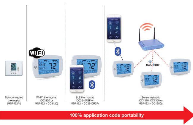
Texas Instruments has developed an entire ecosystem or portfolio around the SimpleLink SDK to facilitate the design with the MSP432P401 microcontrollers. Figure 13 shows an example of what has been said previously. As we can see, if a thermostat has been developed and if it is desired to add a wireless connection, we should only add to the original code the functions (libraries) and hardware required for the desired application. SempleLiknk suporter for WiFi, Bluetooth, Sub 1-GHz connections. This allows code reuse and scalability at 100%.
As a conclusion, we can say that knowing an ARM microcontroller is a matter of practice and also know the terminology that is around ARM microcontrollers. In the following articles we will make use of the different features offered by the ARM MSP432P401 microcontroller and the SKD SimpleLink.
