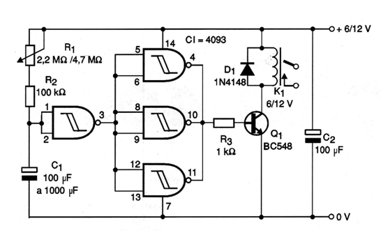
When we connect the power supply of the circuit shown in the figure the capacitor is discharged and thus the pin 2 of the port connected as inverter is practically at the logic low level. That means your output is at the high level. This output is connected to the other three ports that function as a buffer-inverter by energizing the transistor. With the input of these three ports at the high level, its output remains at the low level and thus the transistor in the cut. The relay will open under these conditions. When the capacitor load reaches the point where the port on which it is connected recognizes as a high level, the switching takes place and with that the output of the three ports used as buffer goes to the high level too, exciting the relay that closes the contacts. The time delay is therefore given by the time the capacitor takes to charge from zero to approximately 1/3 of the supply voltage. With a potentiometer of 2.2 M ohm and a capacitor of 2 200 uF one can get timings of more than 1 hour.