
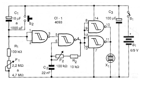
The circuit shown in the figure activates a relay that can charge higher power appliances, even connected to the power grid. Its working principle is simple to understand. When power is established, capacitor C1 charges slowly through R1 and P1 so that the initially high voltage at the inverter port input slowly drops.
The instant the door interprets the voltage as a logical level change, the low level of its output goes to the high level. This logic level is then inverted by the other three ports of the same integrated circuit, which are connected in parallel. With this in the output of the ports and in the base of transistor Q1 that is a PNP, we have the presence of a low level.
This level takes the transistor to saturation by activating the relay. To reset the circuit, simply press and hold the pressure switch S2 for a moment.
The capacitor C1 determines the range of timings that can reach more than 1 hour with 4.7 M ohms and 1 000 uF. The relay must be of the sensitive type with 50 mA of coil and voltage as used in the power supply.
Material list
CI-1 - 4093 - CMOS integrated circuit
Q1 - BC558 or equivalent - general purpose PNP transistor
D1 - 1N4148 - general purpose diode
R1 - 100 k ohm x 1/8 W - resistor - brown, black, yellow
R2 - 2.2 k ohm x 1/8 W - resistor - red, red, red
P1 - 2.2 M ohm at 4.7 M ohms - lin or log potentiometer
C1 - 10 to 1000 uF x 12 V - electrolytic capacitor
C2 - 100 uF x 16 V - electrolytic capacitor
K1 - 6 or 12 V relay - 50 mA coil
S1 - Single switch
S2 - Pressure switch NA
Several:
6 or 12 V source (batteries, battery or source), printed circuit board, wires, solder, button for P1, etc.


