
This circuit is used to indicate whether the voltage available on a power grid is 110 V/117 V or 220 V. It is only suitable for high voltages and can be adjusted to indicate voltages up to 500 V.
The indicator element is a neon lamp, and its use is very simple: we connect the probes in the network and we turn P1 until the lamp comes on. The point at which this occurs indicates whether the voltage is 110 V or 220 V, as set in the scale of the potentiometer itself.
In figure 1 we have the complete diagram of the apparatus and in figure 2 the actual assembly aspect.
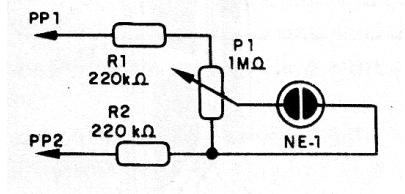
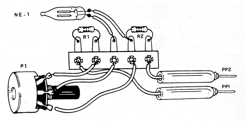
As it is an appliance that is connected to the power grid, it must be enclosed in a plastic box to avoid the danger of shocks. The resistors provide some protection and current limitation for the internal components.
The neon lamp can be of any type without the internal resistor that some have. Calibration is done as follows: connect PP1 and PP2 to a 110 V outlet and mark the scale point of the potentiometer at which the lamp lights up. Then do the same in a 220 V outlet, noting the new point.
To use, simply plug into the network and turn P1 until the lamp turns on. This will occur near the 110 V or 220 V mark as the case may be.
Material list
NE-1 - Neon lamp NE-2H or equivalent
P1- 1 M ohm potentiometer
R1, R2 - 220 k ohm x 1/8 W- resistors- red, red, yellow
PP1, PP2 - Probes or plug
Miscellaneous:
Button and scale for potentiometer, terminal bridge, wires, solder, mounting box, etc.


