
This circuit generates a signal from 3 to 10 MHz and can be used as the basis for an experimental short wave transmitter. The circuit also serves as a signal injector.
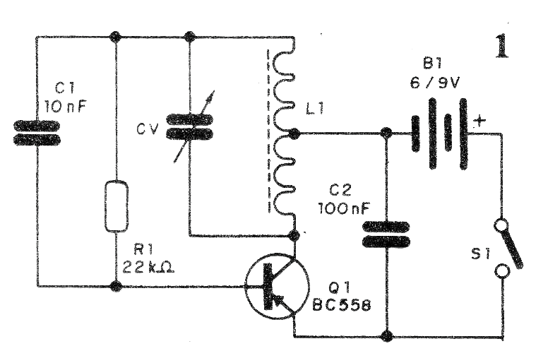
What we have is basically a Hartley oscillator where the frequency is determined by L1 and CV. In the CV capacitor we make the frequency adjustment. The range will depend on the coil which can have from 20 +20 turns of wire 28 in a ferrite rod up to 30 +30 turns.
The variable capacitor can be obtained in old medium-wave radios and the circuit power can be made with voltages of 3 to 6 V obtained from cells, a power source or a battery of 9 V.
Modulation of the signal can be made by applying an audio signal at the base of the transistor, for example a ceramic microphone. An antenna attached to the transmitter's collector enables transmission of signals to a receiver within a few meters.
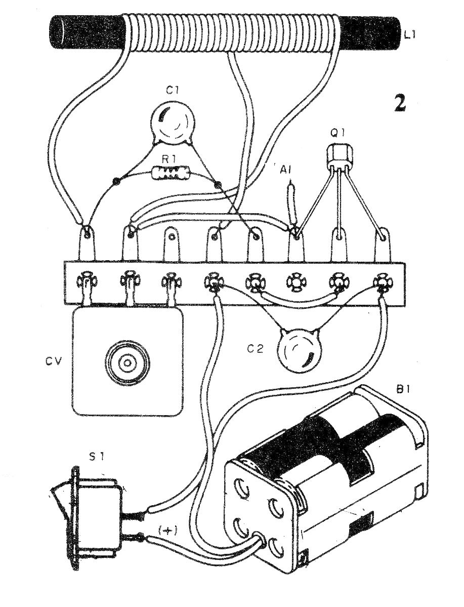
The circuit is shown in figure 1 and the mounting on a terminal strip in figure 2.
Material list:
Q1 - BC558 or BD136 - PNP transistor
R1- 22 k ohm - resistor - red, red, orange
C1- 10 nF - ceramic capacitor
C2- 100 nF - ceramic capacitor
CV - variable capacitor - see text
B1- 3 to 6 V - 2 or 4 cells or 9 V battery
S1- On/Off switch
L1 - Coil - see text
Miscellaneous:
Terminal strip, battery holder, ferrite stick, button for variable, wires, solder, etc.


