
The purpose of this circuit is to generate a signal that can be picked up between the channels 2 and 5 of a common analogue television, and possibly with less intensity, between the channels 7 and 13.
This allows you to approach a television from a distance of 3 or 4 meters and turn on your generator, causing interference that causes the image of a program to disappear or bars are produced on the screen. The effect depends on the signal from the station being interfered with.
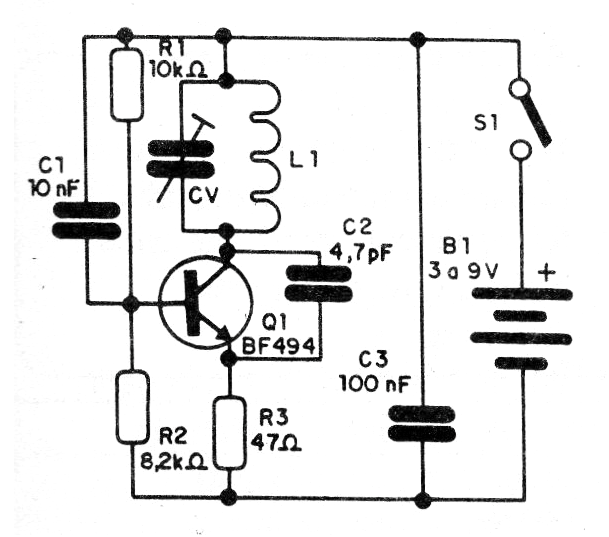
The generator can also be used for testing a TV's operation when there are no nearby stations. In figure 1 we have the complete diagram of the generator.
The arrangement of the components on a terminal strip is shown in figure 2.
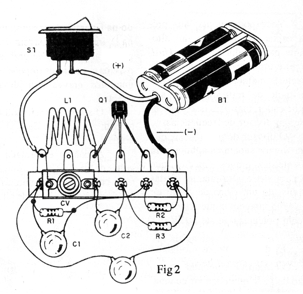
The coil is formed by 3 or 4 turns of common wire with a diameter of 1 cm without core. The old porcelain trimmer, shown in figure 2, can be replaced by a modern type of plastic and its value is not critical, being able to be between 15 and 40 pF of maximum capacitance.
The capacitors must be ceramic and the power can be made with voltages from 3 to 9 V. A wire of 15 to 30 cm can be connected to the collector of the transistor, working as an antenna.
Material list
Q1- BF494 - RF NPN transistor
S1- Single switch - optional
B1- 3 to 9 V- batteries or battery
L1- Bobina- see text
CV - trimmer - see text
C1- 10 nF- ceramic capacitor
C2- 4.7 pF-ceramic capacitor
C3 - 100 nF- ceramic capacitor
R1- 10k ohm x 1/8 W - resistor - brown, black, orange
R2 - 8.2 k ohm x 1/8 W- resistor - gray, red, red
R3 - 47 ohm x 1/8 W- resistor - yellow, violet, black
Miscellaneous:
Terminal bridge, battery holder or battery connector, wires, solder, etc.


