
Using a car ignition coil or even a "fly back" TV transformer, the figure circuit can generate voltages between 7,000 and 30,000 volts for experiments with high voltages and static charges.
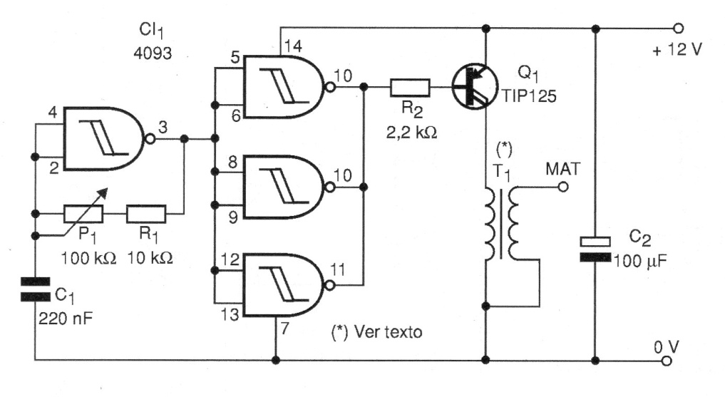
The circuit consists of a power inverter in which the control of the frequency that provides greater efficiency is done in P1.
The transistor must be provided with a good heat radiator and power must come from a source with at least 1 A current capacity.
In the case of using a fly back to T1, it must be of the exposed core type so that we can wrap the primer as shown in the figure.
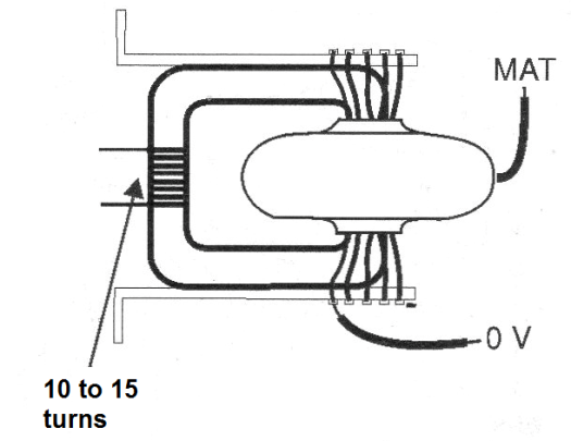
This primary is formed by 10 to 15 coils of common thread 22 with plastic cover. The maximum care must be taken when handling the machine, as the shocks produced in case of accidental contact with the MAT terminal are very unpleasant.
Never use transformerless sources and always be careful of any exposed parts of the circuit. It is recommended to mount it in a wooden or plastic box. To use, set P1 to obtain the maximum output voltage which can be seen, with a fluorescent lamp approaching the output terminal.
Material list
C I-1 - 4093 - CMOS integrated circuit
Q1 - TIP125 - Darlington PNP transistor
T1 - Car ignition coil or TV flyback transformer
P1 - 100 k ohm - potentiometer
R1 - 10 k ohm x 1/8 W - resistor - brown, black, orange
R2 - 2.2 k ohm x 1/8 W - resistor - red, red, red
C1 - 220 nF - ceramic or polyester capacitor
C2 - 100 uF x 25 V - electrolytic capacitor
Several:
Power supply, printed circuit board, mounting box, knob for potentiometer, wires, solder, etc.


