
In figure 1 we show a simple photoelectric circuit that can be used both in alarms and in demonstrations.
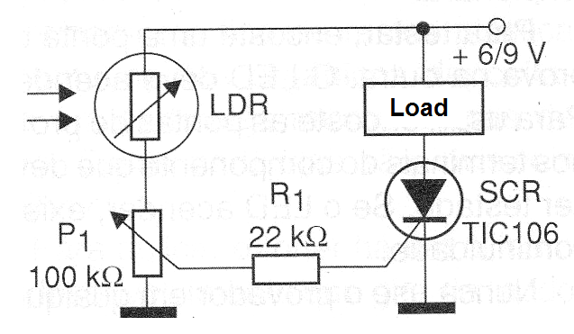
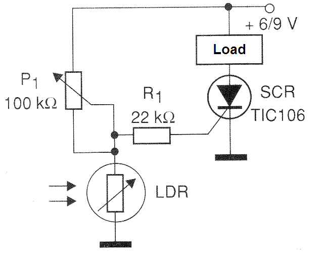
This circuit triggers a relay when a pulse of light hits the sensor, which is nothing more than a common LDR. Changing the position of the sensor, as shown in figure 2, the alarm will fire when we shade it.
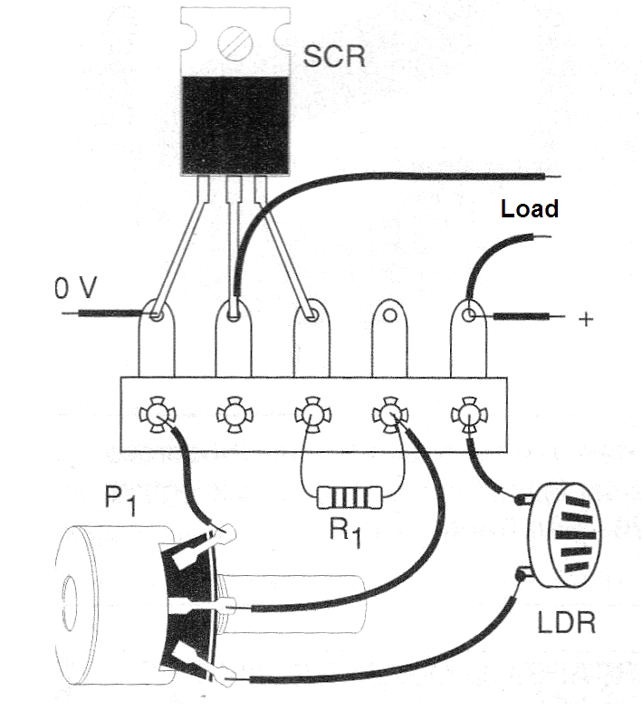
As it is very simple circuit, its assembly can be made based on a bridge and terminals, as shown in figure 3.
The supplied load can operate with currents up to 3 A for the indicated SCR, but above 500 mA it must be mounted on a heat radiator.
It is also important to note that there is a 2 V voltage drop in the SCR when it trips, which means that the load gets 2 V less than the power when the trip occurs.
Thus if the load is 6 V it is necessary that the circuit is supplied with at least 8 V. In this case, a voltage of 9 V is ideal. For a load of 12 V the small difference can be disregarded if it works well with 10 V.
P1 adjusts the sensitivity. For greater directivity and sensitivity the LDR can be installed in an opaque tube.
We note that this circuit has a lock. When it fires by light or shadow, the SCR stays on even after the light or shadow has been removed from the sensor. To disconnect the circuit you must interrupt its power for a moment.
Material list
SCR - TIC106 (any suffix) - silicon controlled diode
LDR - any common LDR
Load - see text
P1 - 100 k ohms - trimpot or potentiometer
R1 - 22k ohms x 1/8 W - resistor - red, red, orange
Miscellaneous:
Power supply, terminal bridge, heat radiator for SCR, wires, solder, etc.


