
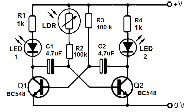
The previous circuit can be controlled by light if we use the LDR as sensor.
It is a multivibrator where the transistors are constantly changing their state of conduction according to the values of capacitors and resistors.
In this case, we have a sensor, the LDR which changes the resistance of one of the branches of the multivibrator in order to modify the speed of the blinks.
In Figure 1, we have the diagram of the light-controlled flasher.
The assembly on the breadboard is shown in Figure 2.
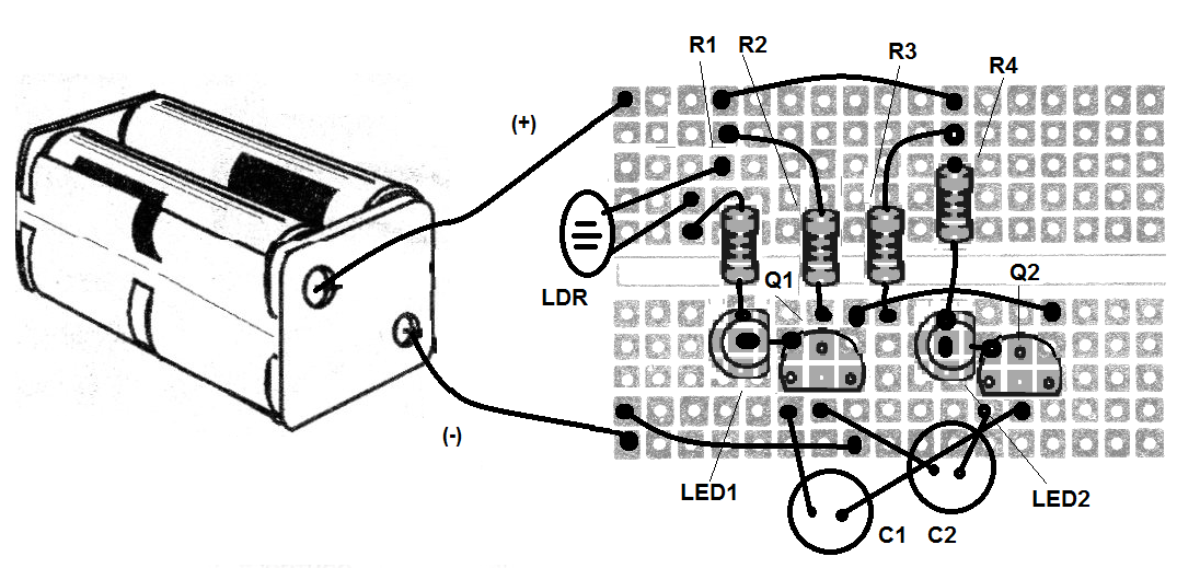
In the assembly, observe the position of the transistors and the LEDs, because if they are inverted the circuit does not work.
If you want, try other value capacitors to see how they influence the speed of the blinks.
Material list
Q1, Q2 - BC548 - NPN transistors
LED1, LED2 - Common LEDs
LDR - Common LDR
R1, R4 - 1k ohm - resistor - brown, black, red
R2, R3- 100 k ohm - resistor - brown, black, yellow
C1, C2 - 4.7 uF - electrolytic capacitors
B1 - 6 V - 4 batteries
Miscellaneous:
breadboard, battery holder, wires, etc.


