
Depending on the transistor used, this power supply can provide from 50 mA to 100 mA of 3 or 6 V under voltage, which is used to power small electronic devices, such as battery radios, calculators, etc. Excellent filtration prevents rumbling from radios and other small stereos.
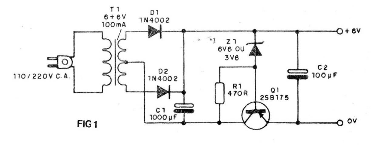
In this assembly, you can use PNP scrap transistors, obtaining with them an excellent regulation of the output voltage of its source. For small power types, such as 2SB175, OC74, 2SB54, the indicated maximum current is 50 mA, but for larger transistors such as AC128 or AC188, you can require up to 100 mA without problems.
Of course, modern transistors such as the BC557 or BC558 can be used in this source that can reach 500 mA with the BD136, provided it is mounted on a heat radiator.
The zener diode determines the output voltage. For a zener of 400 mW x 3V6, we will have an output voltage of 3V, and for a zener of 400 mW x 6V6, we will have an output voltage of 6V. In both cases, the transformer has secondary winding of 6 + 6 V with 50 mA or 100 mA of current.
As this current is low, the transformer has small dimensions and may, together with the other components, be installed in a plastic battery eliminator box.
The primary of the transformer will be chosen according to the network voltage, i.e., 110 or 220 V.
ASSEMBLY
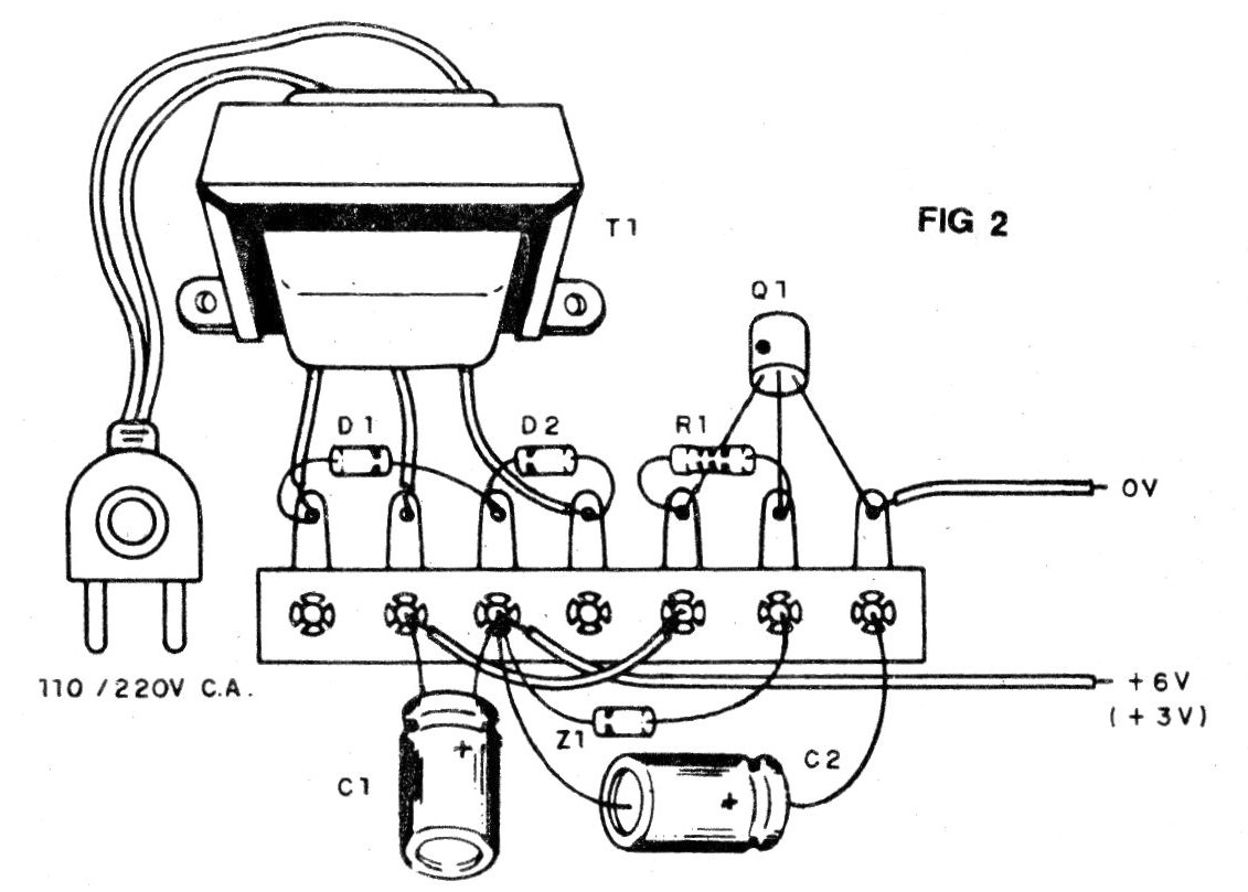
In Figure 1, we give the complete circuit of the microphone, and in Figure 2, the aspect of its assembly in terminal bridges. Note that the transistor has its collector identified by a mark or dot.
The filter capacitor may be from 1 000 to 1 500 uF with insulation voltage of 16 V or more.
The rectifier diodes can be 1N4002 or higher voltage equivalents, such as 1N4004, BY127 etc.
Observe the polarity of the zener diode of 400 mW which will be chosen depending on the output voltage. The output electrolytic (C2) has a working voltage of 6 V or more.
The resistor is 1/8 to 1/2 W with any tolerance.
It is important to observe the polarity of the output wires, since the supplied devices do not allow inversions.
TEST AND USE
To test, simply connect the unit to the socket and with the help of a multimeter measure the output voltage, which must be according to the predicted value, i.e., 3 or 6 V.
Once the operation has been verified, it is only necessary to make the connection with a suitable plug to the device to be fed. Take the utmost care of the device to be fed, as far as the current that the source is able to supply.
MATERIAL LIST
Q1 - any general purpose PNP transistors (2SB54, 2SB75, AC188, etc.)
D1, D2 - 1N4002 or equivalent - diodes
Z1 - zener of 3V6 or 6V6 x 400 mW
T1 - transformer with primary according to the local power grid and secondary of 6 + 6 Vx100 mA
C1 - 1000, uF x 16 V - electrolytic capacitor
C2 - 100, uF x 6 V - electrolytic capacitor
R1 - 470 ohm - resistor (yellow, violet, brown)
Miscellaneous:
Power cord, terminal bridge, mounting box, wires, welding, etc.


