
This preamplifier, which can work with a very small battery (AAA), mounted in a small box, will be inserted directly into the input of an amplifier. The signal source can then be connected to the input of the preamplifier in good yield.
The circuit is ideal for low-gain (dynamic) microphones that can not directly excite the input of an amplifier or inductive transducers.
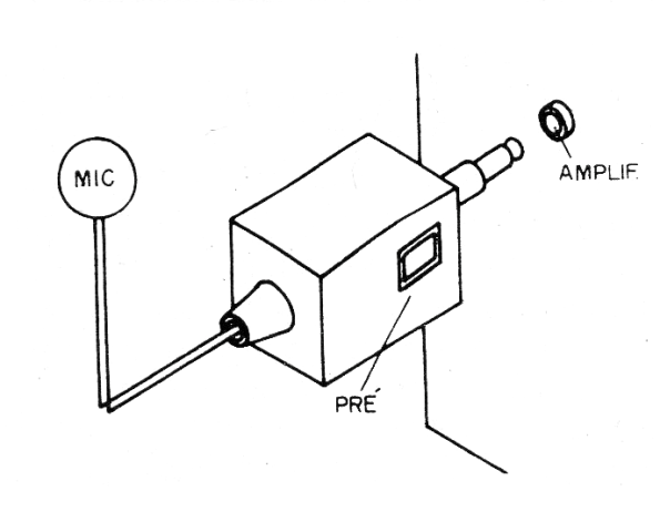
The low current consumption guarantees an excellent range of power even if it is a low current battery. In figure 1 we show how this preamplifier can be mounted, with a fixed plug to fit the input of the power amplifier.
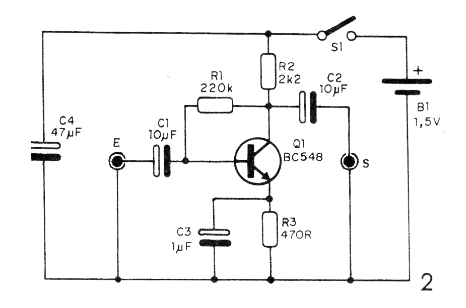
In figure 2 we have the complete diagram of the preamplifier.
In figure 3 we have a suggestion of printed circuit board for the assembly of the preamplifier.
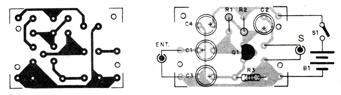
The output plug must match the input of the amplifier and the input jack according to the signal source. R1 should eventually be changed between 100k and 1M for the best performance without distortion, depending on the signal source.
Because 1-cell holders are difficult to obtain, power wires can be soldered directly to the cell.
Material list
Q1 - BC548 - NPN general purpose transistor
B1 - 1.5 V- AAA battery
S1 – On-Off switch
C1, C2 - 10 uF x 3 V or more - electrolytic capacitors
C3 - 1 uF x 3 V or more - electrolytic capacitor
C4 - 47 uF x 3 V or more - electrolytic capacitor
R1 - 220k ohm x 1/8 W- resistor - red, red, yellow
R2 - 2.2 k ohm x 1/8 W - resistor - red, red, red
R3 - 470 ohm x 1/8 W- resistor - yellow, violet, brown
Miscellaneous: printed circuit board, input jack, output plug, mounting box, wires, solder, etc.


