
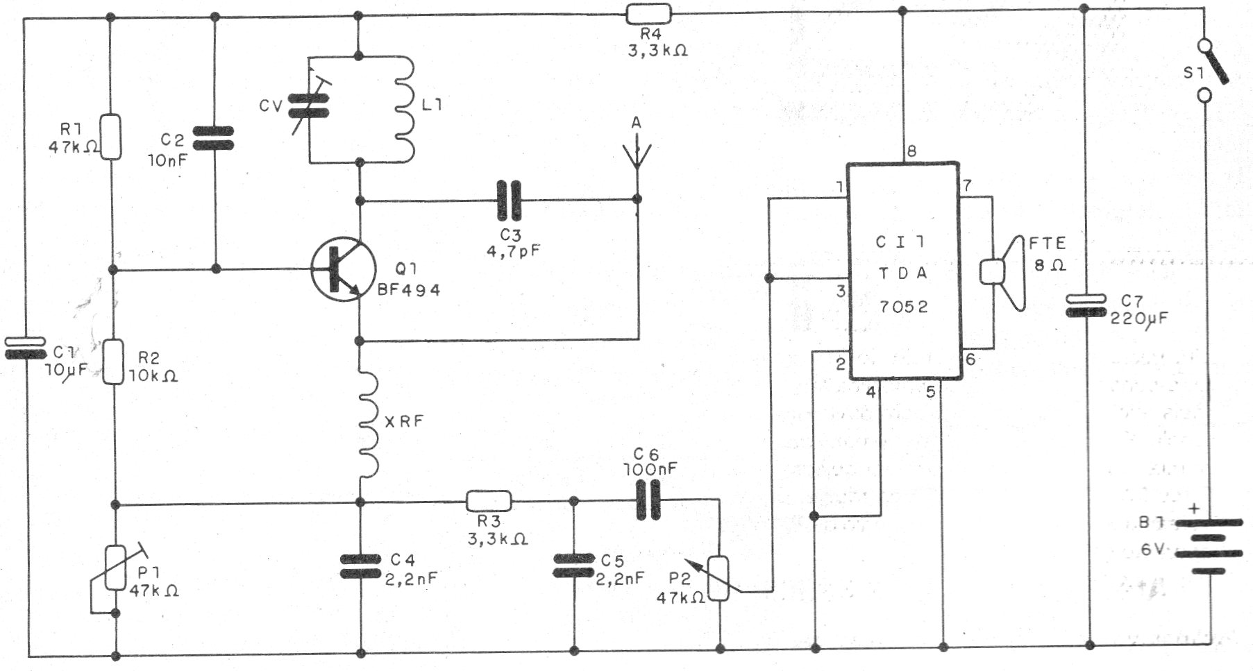
This receiver can pick up the local FM stations and in the range of VHF airplanes, utilities, etc. The circuit is very sensitive and uses integrated amplifier with good power to excite a speaker.
We describe a small super-regenerative receiver for the VHF and FM range, depending on the coil used, with excellent sensitivity.
The circuit is powered by 4 batteries and the components used are common, some may even be harvested from scrap metal.
The circuit uses a super-regenerative detector stage that is characterized by its great sensitivity, although the selectivity is not very large, which will make it difficult to capture weak stations in places where there are many stations nearby.
In figure 1 we have the complete diagram of the receiver.
The printed circuit board for the assembly is shown in figure 2.
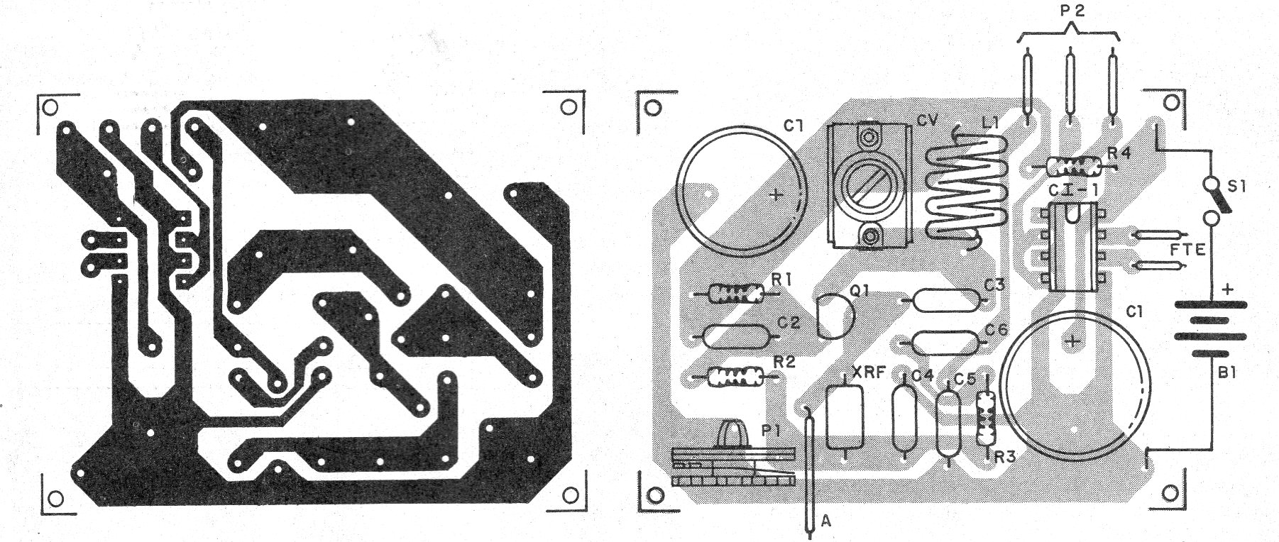
In the assembly, observe the position of the transistor and the integrated circuit, as well as the polarity of the electrolytic capacitors.
The resistors are 1/8 W with any tolerance and the electrolytic capacitors to 6 V or more.
For the FM range the coil consists of 4 turns of enameled wire 26 or 28 AWG in the form of 1 cm without core. Hard wire (gray) can also be used.
For the VHF range use 2 or 3 turns of the same wire with the same diameter.
The receiver will then tune stations between 100 and 140 MHz.
The antenna is of the telescopic type or a vertical rigid wire of 40 to 120 cm in length.
XRF can be made by winding 40 to 50 turns of very fine enameled wire (30 or 32) on a toothpick.
The variable capacitor must be of the type used in low-capacity FM radios with low capacitance, and the types used in AM radios that are of greater capacitance should not be confused.
To use, set CV and P1 at the same time for best reception and volume at P2.
Material list
CI-1 - TDA7052 - integrated circuit
Q1 - BF494 - RF NPN transistor
L1 - Coil - see text
CV - variable capacitor - see text
XRF - Shock of 47 to 100 uH - see text
FTE - 4 or 8 ohms - speaker
S1 – On-Off switch
B1 - 4 small batteries
A - antenna - see text
P1 - 47k ohms - potentiometer
P2 - 47k ohms - potentiometer
R1 - 47 k ohms - resistor - yellow, violet, orange
R2 - 10 k ohms - resistor - brown, black, orange
R3, R4 - 3k3 ohms - resistors - orange, orange, red
C1 - 10 uF - electrolytic capacitor
C2 - 10 nF - ceramic capacitor
C3 - 4.7 pF - ceramic capacitor
C4, C5 - 2n2 F - ceramic or polyester capacitors
C6 - 100 nF - ceramic or polyester capacitor
C7 - 100 uF - electrolytic capacitor
Several:
Printed circuit board, battery holder, mounting box, wires, solder, etc.


