
With this circuit we can control the brightness of small 12 V lamps, the speed of small AC motors or even the temperature of AC elements powered by alternating current. The circuit has numerous practical applications and is quite simple.
As can be seen from figure 1, the conduction angle of the SCR is given by the incidence of the pulses, generated by the unijunction transistor that functions as a relaxation oscillator.
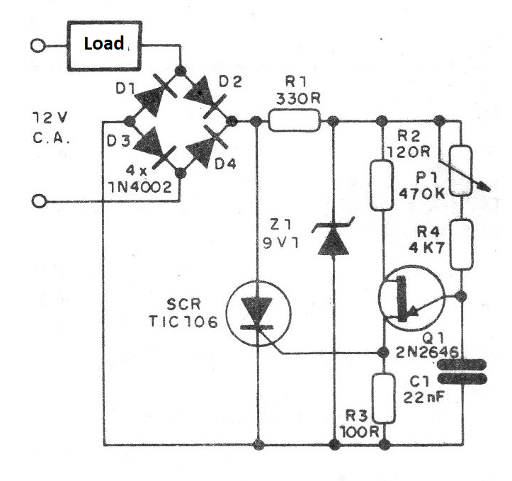
By controlling the frequency of the oscillator we can obtain a variation of the power applied to the load and with this the desired control.
In figure 2 we have the small printed circuit board suggested for this project.
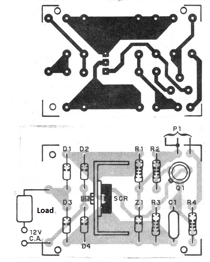
The resistor R1, with the help of Z1, keeps the voltage in the oscillator constant, and rectification by the diode bridge allows full wave control. The diodes used are 1A, which is the maximum current suggested for the control. Note that the SCR must be fitted with a heat radiator.
The potentiometer P1 of 470 k can be both linear and log, depending on the desired variation. Alterations of C1 can be made experimentally in order to modify the range of actuation of the control. The resistor R1 must be ½ W, while the others may be 1/8 or ¼ W. For larger operating voltages, changes of R1 must be made in addition to the use of an SCR with maximum compatible voltage.
Please note that this control only works properly on AC circuits.
MATERIAL LIST
SCR - TIC106 or equivalent for 50 V
D1 to D4 - 1N4002 - silicon rectifier diodes
Q1 - 2N2646 - unijunction transistor
P1 - 470 k - potentiometer
Z1 - 9V1 - Zener diode of 400 mW
R1 - 330 ohm x ½ W - resistor (orange, orange, brown)
R2 - 120 ohm x 1/8 W - resistor (brown, red, brown)
R3 - 100 ohm x 1/8 W - resistor (brown, black, brown)
R4 - 4k7 x 1 / 8W - resistor (yellow, violet, red)
Miscellaneous: printed circuit board, mounting box, pushbutton for P1, wires, solder, heat radiator for SCR etc.


