
The purpose of this didactic project is to show how an astable multivibrator can operate at a high frequency and by applying its signals to a transducer, we can get sounds. How to change the frequency of these sounds using a sensor (LDR).
An astable multivibrator can be used to generate a signal in the audio frequency band and by applying to a transducer for sound. In this project, we go further, showing how we can add an LDR to the RC circuit that determines the frequency and with that control it from the light.
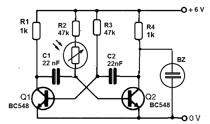
In the circuit, we add the LDR to one of the branches of the multivibrator so that it controls only part of the frequency, with the conduction of one of the transistors. We see that when the resistance of the LDR decreases in the presence of light, the time constant decreases and with that the frequency becomes higher and the sound emitted is more acute.
An interesting possibility of circuit change is to use two LDRs, one in series with each base resistor of the multivibrator transistors.
Assembly
In figure 1 we have the complete diagram of our astable light-controlled multivibrator.
The assembly is made in the protoboard with the arrangement shown in figure 2.
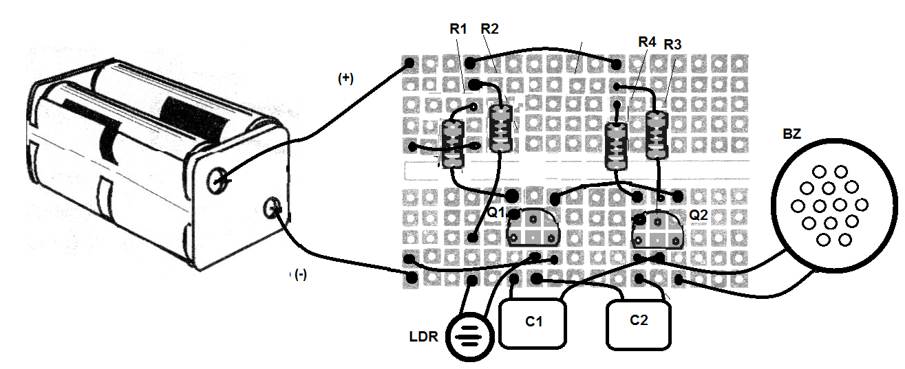
When assembling, observe the position of the transistors and the polarity of the batteries supplying the circuit. The transducer is connected to the collector of one of the transistors, where we remove the signal for playback.
Note that this signal can also be removed from the collector of the other transistor. Observe carefully the values of the resistors that are given by the colored bands.
Material list
Q1, Q2 - BC548 - NPN transistors
LDR - Common LDR
R1, R4 - 1k ohm - resistor - brown, black, red
R2, R3-47 k ohm - resistor - yellow, violet, orange
C1, C2-22 or 47 nF - electrolytic capacitors
B1 - 6 V - 4 batteries
BZ - Piezoelectric transducer
Several:
Protoboard, batteries holder, wires, etc.


