
Assemble a simple experimental design of a radio wave transmitter that uses a motor to produce them (*). The circuit is based on experiments from the early radio era.
(*) Like in the earlier days of radio.
Early in the radio era, when there were no components such as valves and transistors to generate waves, a first station in New York used a motor as a transmitter.
The motor spinning at a very high speed produced an alternating voltage of a few hundred kHz which, after passing through a modulation circuit, was drawn to an antenna.
Of course the system is no longer used, but we can make a small experimental transmitter that uses a motor, working as a dynamo to generate radio signals.
A configuration like that shown in figure 1 could be used in a first project.
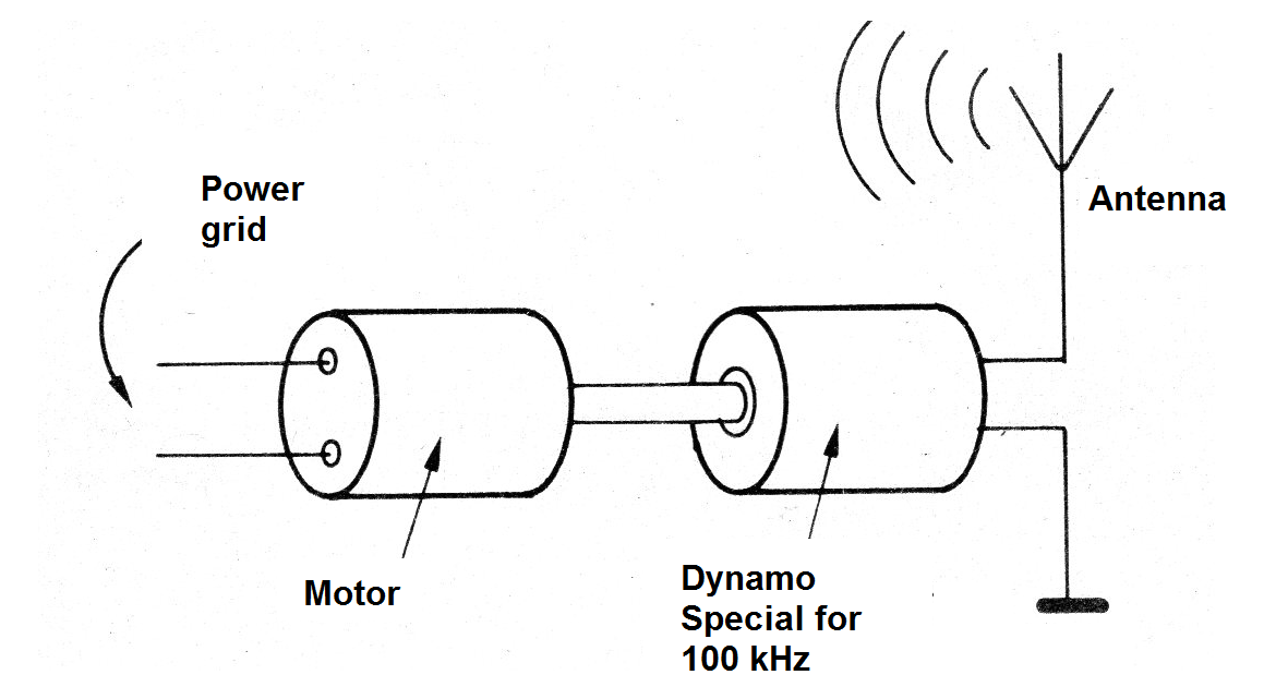
In the original version is used a dynamo that generates a current of 100 kHz.
In our case, we can use a small motor and what is used is the rapid switching of brushes that, charging an inductive circuit, generates a signal rich in harmonic, which applied to an antenna results in radio waves.
In our case, we will use an improved configuration that is shown in figure 2.
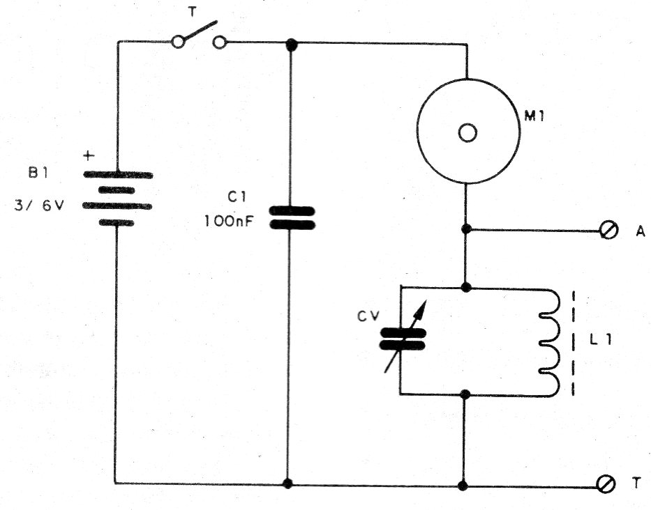
In this circuit, the switching of the motor brushes generates a signal rich in harmonics, which applied to a tuned circuit causes only a signal of a certain frequency to be taken to an antenna.
The circuit transmits continuous waves (CW), being able to be used in telegraphic transmissions (see other articles in the site).
The range is a few meters, and reception of the signal can be done in a medium wave radiate.
The assembly can be done using a small insulated terminal strip, as shown in figure 3.
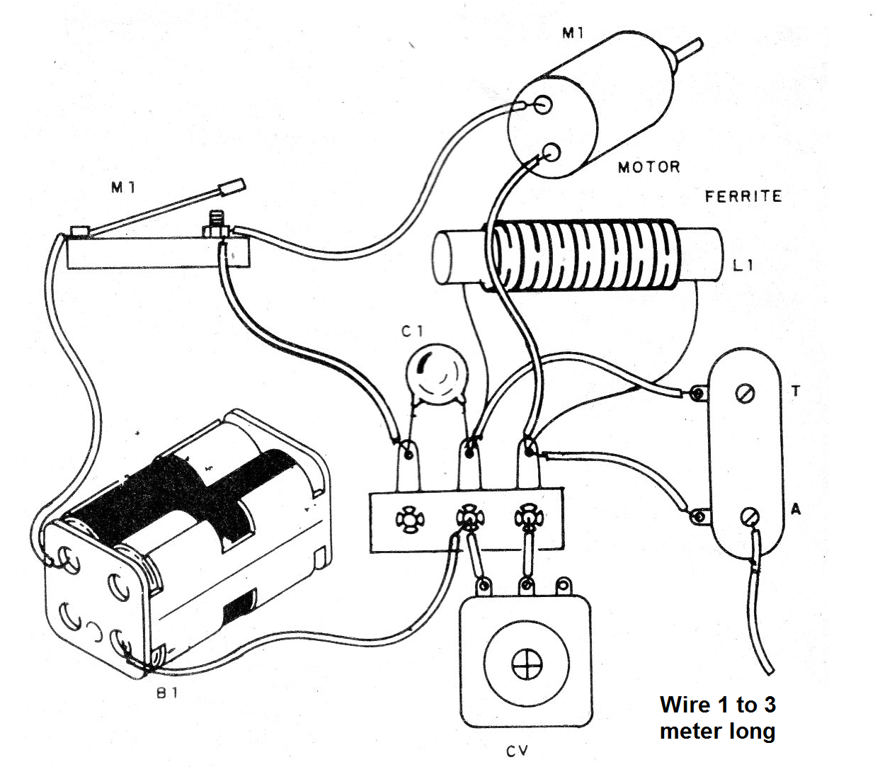
The coil consists of 60 to 100 turns of fine enamelled wire (28 or 30 AWG) on a ferrite rod.
The CV variable capacitor can be harnessed from any out-of-use midrange radios.
The antenna consists of a piece of ordinary wire from 1 to 5 meters in length.
The motor can be of any type for 2 or 4 small batteries.
Material list
M1 - 3 or 6 V motor
CV - variable capacitor - see text
L1 - Coil - see text
B1 - 3 or 6 V - 2 or 4 small batteries
T – Morse key
C1 - 100 nF - ceramic capacitor
Several:
Terminal stgrip, battery holder, wires, solder, etc.


