
Voltage regulators from 5 to 15 V for 1 A currents can be easily obtained in the form of integrated circuits. This is the case with the 78xx series. This source can provide 5 to 15 V of output voltage according to the IC used. The "xx" indicates the output voltage.
For example, the integrated circuit 7806 provides a voltage of 6 V. In figure 1 we have the basic configuration for this source.
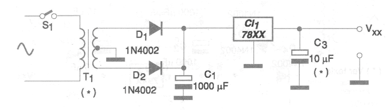
We have seen some important facts about this circuit, which can be very useful to the developer. There are versions with suffixes "L" that are presented in SOT-54 enclosures for currents up to 200 mA. They can be used in cases where we want lower output current.
The output decoupling capacitors should have lower values in some cases, depending on the suffix of the IC and the manufacturer. We can increase the output voltage of a 78xx series IC in two ways. One is to add common diodes or zener diodes to the reference terminal, as shown in figure 2.
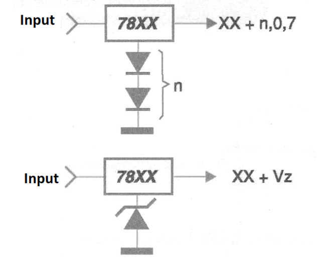
In this circuit, ordinary diodes, polarized in the direct direction add 0.6 V to the internal reference diode, thus increasing the output voltage. Another way of increasing the output voltage is by using a resistive divider, as shown in figure 3.
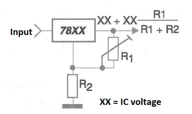
In figure 4 we show a printed circuit board for implementation of this source.
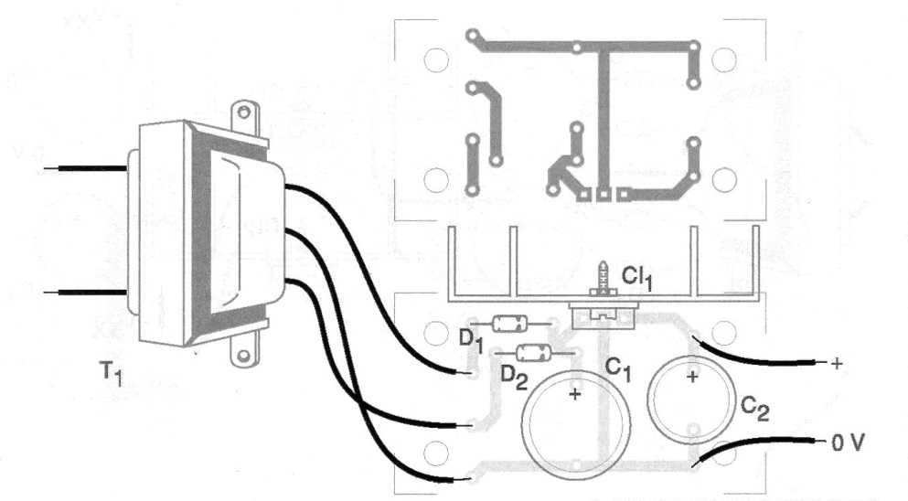
The integrated voltage regulator circuit shall be fitted with a heat radiator.
The transformer must have a secondary voltage at least 2 V higher than the one we want at the output, given by the integrated regulator used. The current should go up to 1 A as desired at the output.
The working voltage of C1 must be at least 60% higher than the rms voltage of the transformer secondary.
Material list
CI-1 - 78xx - integrated circuit voltage regulator - see text
D1, D2 - 1N4002 or equivalent - rectifier diodes
C1 - 1000 uF - electrolytic capacitor
C2 - 10 uF - electrolytic capacitor
S1 – On/Off switch
T1 - Transformer - see text


