
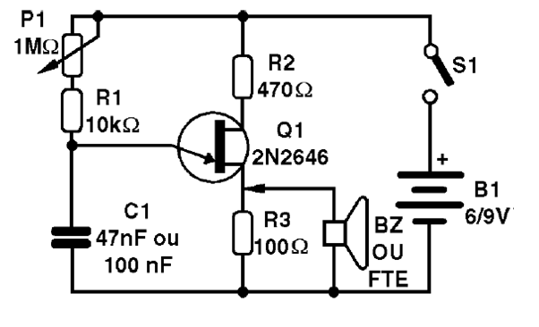
This circuit directly excites a small speaker, producing a sound whose frequency is adjusted by the potentiometer. We can use it in demonstrations, in acoustic classes to teach the difference between bass and treble sounds, or even as part of an alarm circuit. It is a fairly simple audio oscillator that makes use of a single transistor unijunction.
For its simplicity and volume produced in a small speaker, it is more of an experimental setup than for some practical use. We can change the speaker through a 22 ohm resistor and connect this output to an amplifier or even ceramic transducer, thus obtaining greater output power.
In figure 1 we have the complete diagram of our experimental oscillator.
In figure 2 we have the experimental set up based on a terminal strip.
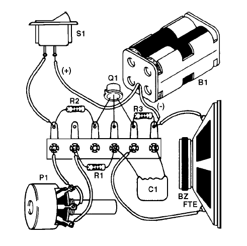
Note the small shoulder on the transistor housing which serves as a reference for its positioning.
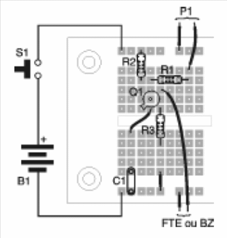
In figure 3 we have the assembly made in a protoboard.
To use the circuit is simple: simply turn on the power and adjust the frequency of the sound produced in the potentiometer. Note that by rotating the potentiometer slider, decreasing its resistance, the oscillator frequency increases, making the sound sharper.
Change the capacitor value to obtain other frequencies.
If you use small values, the circuit can reach the ultrasonic range, in which case a small piezoelectric tweeter can perform its reproduction for various experiments.
In practice
The observation about the need to have a correct positioning of the unijunction transistor is very important for readers who intend to become electronic technicians. In fact, a good part of the electronic components is of the polarized type, that is, they have the right position for the assembly.
Highlights, marks, spots, and other features are used to show how the component should be positioned. In the exchange of any component of a computer or peripheral, the technician must be attentive to this detail.
MATERIAL LIST
Q1 and Q2 - 2N2646 - unijunction transistors
P1 and P2 - 100 k ohms- potentiometers
P3 - 22 k ohm - potentiometer
R1 and R2 - 10 k ohm - resistors (brown, black, orange)
R3 and R4 - 470 ohm - resistors (yellow, violet, brown)
R5 and R6 - 100 ohm - resistors (brown, black, brown)
C1 - 47 nF - ceramic or polyester capacitor
C2 - 10 μF - electrolytic capacitor for 16V or more
C3 - 10 nF - ceramic or polyester capacitor
B1 - 9 V - battery or external power supply
S1 – On/Off switch
Miscellaneous: Contact array or universal board, battery holder, buttons for potentiometers, mounting box, wires, etc.


