
This circuit drives a DC motor when the LDR is illuminated. The configuration shown in figure 1 can serve as the basis for a toy, such as a robot that is driven by a headlamp or even a race car.
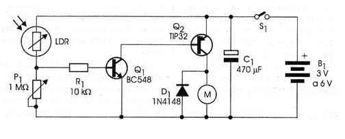
The sensitivity adjustment is made in P1 and for greater directivity in the drive the LDR must be mounted in an opaque tube.
Transistor Q2 shall be provided with a heat radiator if the motor requires a current greater than 200 mA. The reader will realize the need for this heatsink if, by making the circuit work, this component overheats.
In figure 2 we have the assembly of this circuit in a terminal strip, ideal version for students and beginners.
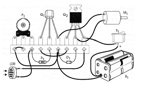
Those who have the resources can prepare the assembly on a printed circuit board. For demonstrations the assembly can be done in a matrix of contacts.
Two or four batteries of any size can be used depending on the motor.
Material list
Q1 - BC548 or equivalent - general purpose NPN transistor
Q2 - TIP32 - PNP power transistor
D1 - 1N4148 - general purpose diode
LDR - round common LDR
P1 - 1 M ohms - trimpot
R1 - 10 k ohms x 1/8 W - resistor - brown, black, orange
C1 - 470 uF x 12 V - electrolytic capacitor
M - 3 to 6 V common motor
S1 - Single switch
B1 - 3 or 6 V - 2 or 4 batteries (see text)
Several:
Terminal strip, battery holder, mounting box, wires, solder, etc.


