
The control of a DC motor directly from digital signals through a digital-to-analog converter can be implemented from the circuit shown in figure 1
.
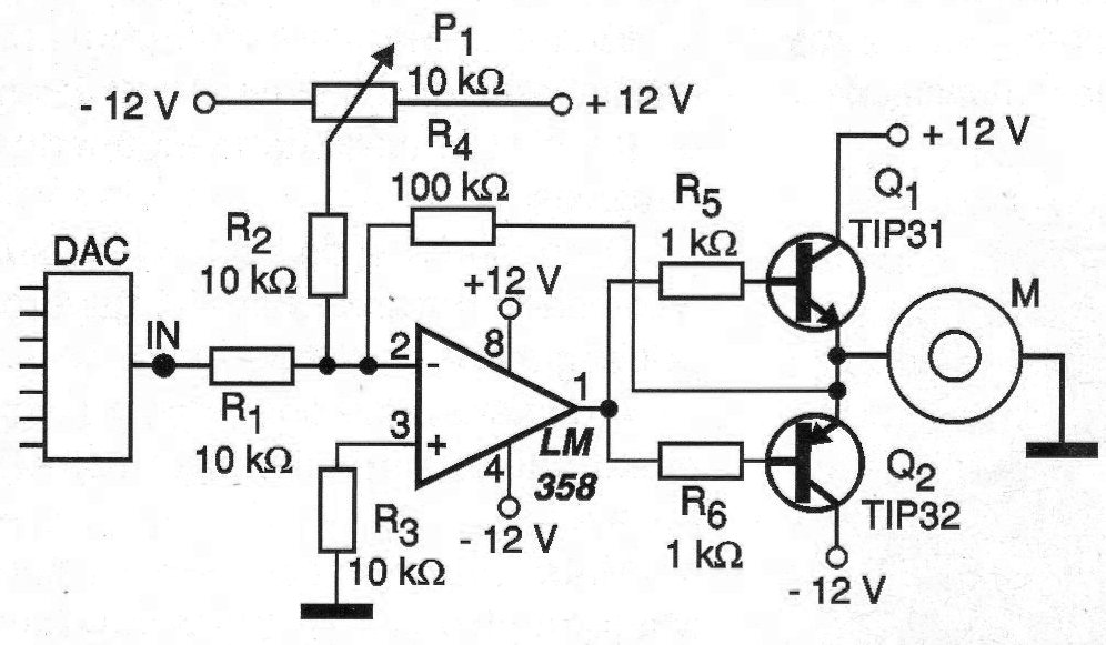
In this circuit, the analog signals (voltage) obtained at the output of the D / A converter will determine the conduction of the transistors and with it both the power applied to the motor and its direction of rotation. The resolution of the D / A converter used will determine the accuracy in the control, remembering that the range of output values will be symmetrical with the center of the scale meaning 0 V or motor stopped. This is because the motor power is symmetrical.
Correct adjustment of this range can be achieved through the trimpot or adjustment potentiometer P1. The circuit is specified for 12 V motors but motors with other voltages in the range of 6 to 15 V can be used. The maximum motor current for the indicated transistors is 2 A.
In figure 2 we have a suggestion of printed circuit board for the assembly of this control.
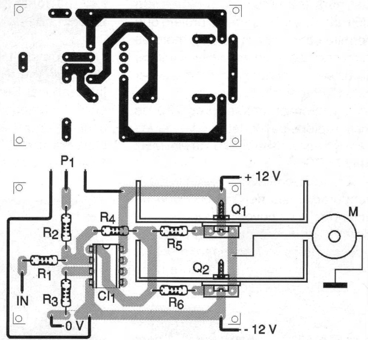
Note that the tracks that work with the most intense currents for the engine must be wider. Operational amplifiers equivalent to the LM358 can be used and the gain of the circuit can be changed in R4.
MATERIAL LIST
CI-1 - LM358 - Operational Amplifier
Q1 - TIP31 - NPN power transistor
Q2 - TIP32 - PNP power transistor
R1, R2, R3 - 10 k ohm x 1/8 W - resistors - brown, black, orange
R4 - 100 k ohm x 1/8 W - resistor - brown, black, yellow
R5, R6 - 1k ohm x 1/8 W - resistors - brown, black, red
P1 - 10 k ohm - trimpot or potentiometer
Several:
Printed circuit board, heat radiator for transistors, wires, solder, etc.


