
One of the most traditional voltage regulator circuits, quite old but still in frequent use even in equipment manufactured today, is the "723" voltage regulator. If the reader needs a good regulated source for the bench, the circuit with the 723 is a good suggestion.
This integrated circuit has a number of features that, with some external components, allow the elaboration of efficient power supplies in a wide range of currents and voltages. In Figure 1 we have a typical high current power supply using this integrated circuit as the base.
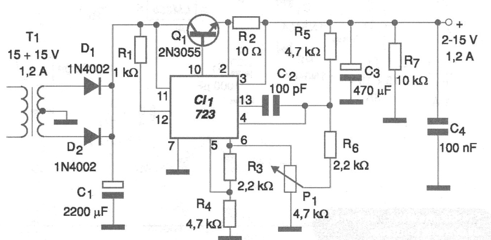
The characteristics of this power supply are:
• Output voltage adjustable between 2 and 15 V
• Maximum output current 1.2 A
As can be seen, transistor 2N3055, which is to be provided with a heat sink, controls the main current, the voltage being supplied as reference by the integrated circuit 723.
In figure 2 we have a suggestion of printed circuit board for the assembly of this power supply.
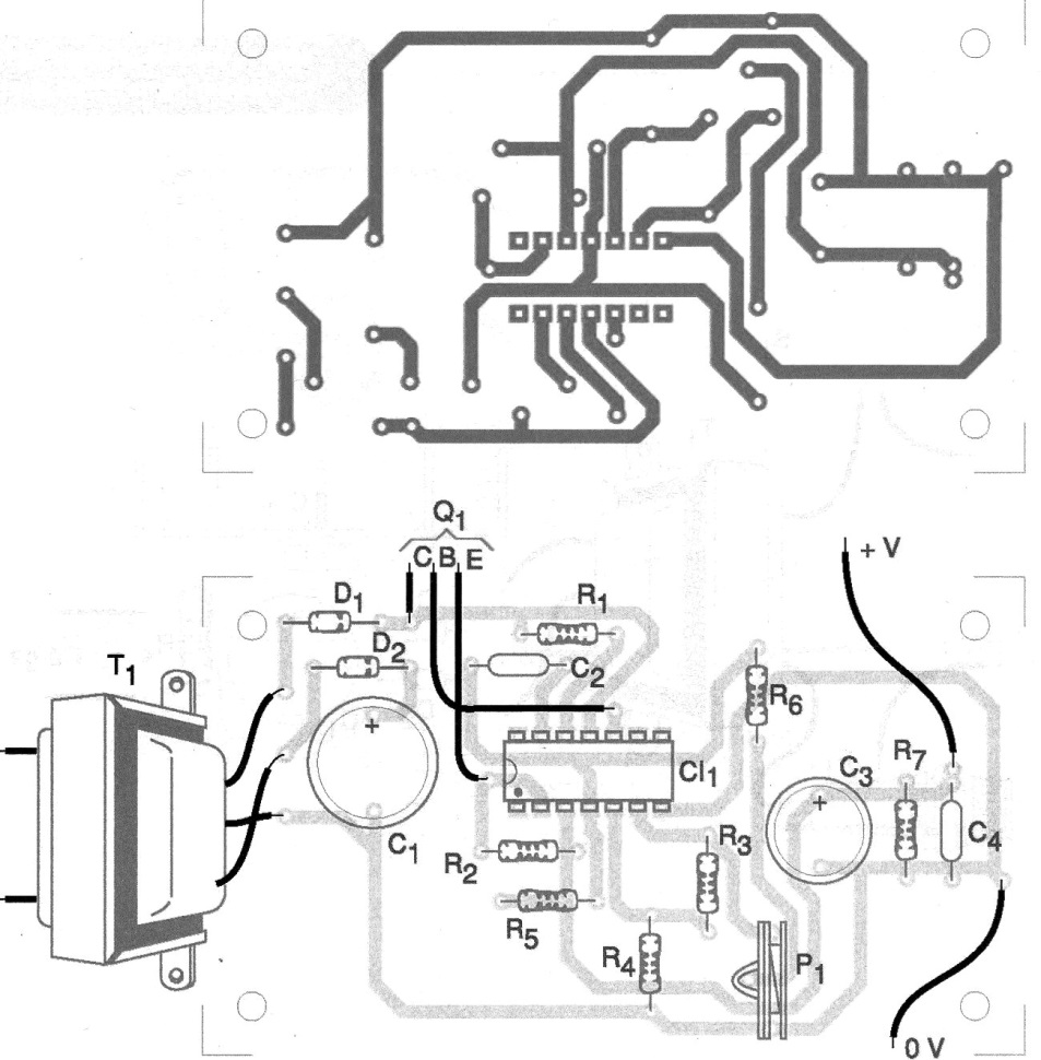
The transformer secondary must supply a voltage of 15 + 15 V with 1.2 A and primary according to the power grid. For filtering, the capacitor C1 must have a working voltage of at least 25 V.
Material list
CI-1 - LM723 - integrated circuit voltage regulator
Q1 - 2N3055 - Power NPN Transistor
D1, D2 - 1N4002 - rectifier diodes
T1 - transformer - 15 + 15 V x 1.2 A
F1 - 1 A - fuse
R1 - 1 k ohm x 1/8 W - resistor
R2 - 10 ohm 5 W - wire resistor
R3, R6 - 2.2 k ohm x 1/8 W - resistor
R4, R5 - 4.7 k ohm x 1/8 W - resistor
R7 - 10 k ohm x 1/8 W - resistor
P1 - 4.7 k ohm - trimpot
C1 - 2 200 uF x 25 V - electrolytic capacitor
C2 - 100 pF - ceramic capacitor
C3 - 470 uF x 16 V - electrolytic capacitor
C4 - 100 nF- ceramic capacitor
Several:
Printed circuit board, heat radiator for Q1, wires, solder, power cable, mounting box, etc.


