
This oscillator can work as the basis for experimental designs of transmitters or as a signal injector. With a small antenna, it can send its signals to a receiver placed within a few meters.
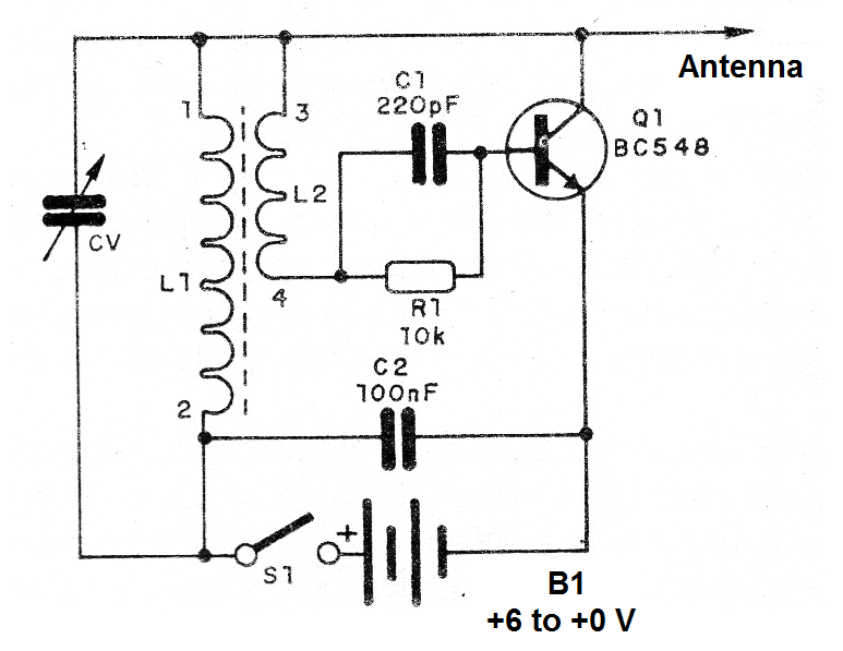
The circuit is powered by voltages from 6 to 9 V by batteries, source or a battery. The components are common. The coil consists of a coil with 100 turns of wire 26 to 30 AWG in a ferrite rod resulting in winding with terminals and 1 and 2 in the diagram and, next to it, a coil with 30 turns of the same wire, resulting in windings with terminals 3 and 4.
The variable capacitor can be obtained on any out-of-use AM radio. The complete circuit of the oscillator is shown in Figure 1.
In Figure 2, we have the assembly using a terminal strip.
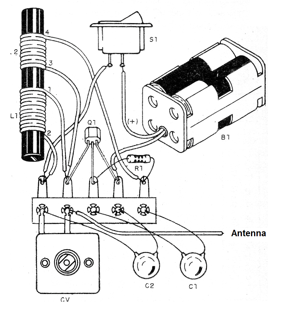
To test, connect a short-wave receiver nearby and try tuning the oscillator to hear its signal. If it does not oscillate, reverse the connections of wires 1 and 2 of the coil.
Material list
Q1- BC548 - general-purpose NPN transistors
L1, L2 - Coils - see text
CV - variable capacitor - see text
S1 - Single switch
B1 - 6 to 9 V - batteries, battery or power supply
R1 - 10 k ohms x 1/8 W - resistor - brown, black, orange
C1 - 220 pF - ceramic capacitor
C2 - 100 nF - ceramic capacitor
Various: terminal strip, battery holder or battery connector, ferrite stick, enameled wires, etc.


