
This small timer can be used in the science lab to time events that do not exceed 2 or 3 minutes, such as chemical reactions, physical phenomena or exposure of plants to light or even photographic plates.
The basis of the design is an RC circuit with neon lamp where the charge time of a capacitor is determined by potentiometer adjustment.
After comparing the times obtained at various positions of the potentiometer with a common clock or timer we can calibrate its scale and thus obtain a timer of good precision.
In figure 1 we have the complete diagram of the apparatus.

The arrangement of the few components in a terminal bridge is shown in figure 2.
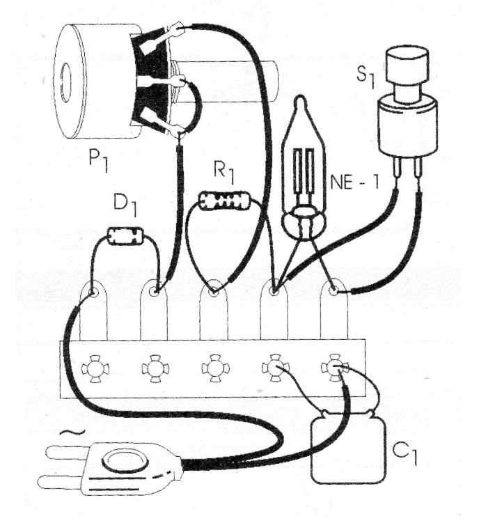
The capacitor C1 must have a working voltage of at least 100 V (in any network) and must be of the polyester type with values between 2.2 and 10 uF. Larger values lead to the possibility of larger timings. Potentiometer P1 is linear of 4.7 M ohms or 10 M ohms.
For operation the procedure is simple: set P1 to the desired time and connect the unit to the outlet. Time will start to count. When the expected time is reached the neon lamp will light up.
To reset the unit or count the time again, press S1 for a moment. The popping sound is the discharge of the capacitor.
MATERIAL LIST
D1 - 1N4007 - silicon diode
NE-1 - common neon lamp
P1 - 4.7 M ohms or 10 M ohms - potentiometer
R1 - 1 M ohms - resistor - brown, black, green
C1 - 2.2 to 10 uF x 100 V (or more) - polyester capacitor
S1 - Pressure switch NA (normally open)
Miscellaneous: terminal bridge, power cable, mounting box, knob and scale for potentiometer, wires, solder, etc.


