
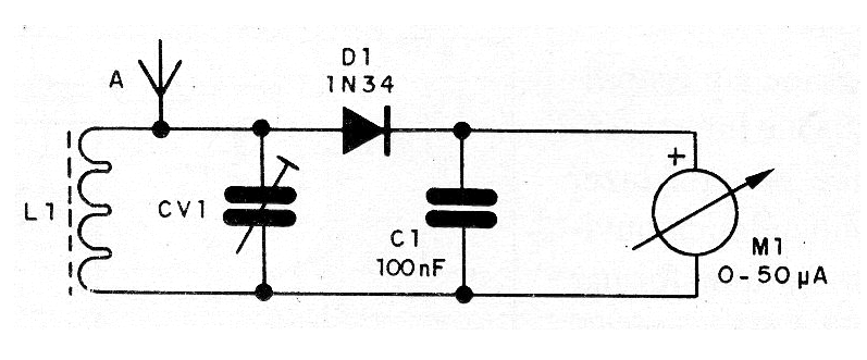
This simple circuit, which does not require power supply, measures the field strength produced by medium and short wave transmitters.
It is a device of great utility in the adjustment and verification of small transmitters and also in the verification of antenna systems.
Depending on the used coil we can measure signals from the medium wave band up to approximately 50 MHz.
The circuit is very sensitive, depending on the indicator instrument used and does not require power, since the power to drive comes from the signal itself captured by the telescopic antenna.
In figure 1 we have the complete diagram of the field strength meter.
In figure 2 we have the assembly based on a small terminal strip.
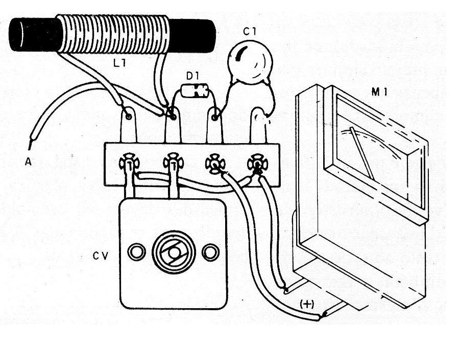
The coil is wound onto a ferrite rod 1 cm in diameter and 10 cm long with wire 28. The number of turns depends on the range:
500 kHz at 2 MHz- 80 turns
2 MHz to 7 MHz - 30 turns
7 MHz at 15 MHz 15 turns
15 MHz at 30 MHz - 10 turns
The antenna is a telescopic type with 60 cm to 1 meter in length and CV is taken from a common AM radio out of use.
The indicator instrument is a 200 uA microammeter that can be obtained from an out-of-use amplifier or recorder. C1 is not critical and the diode can be of any type of germanium.
To test, approach the antenna of a transmitter and adjust CV until the signal is indicated on the instrument.
Material list
D1- 1N34 or equivalent - germanium diode
L1- Coil - see text
CV1- Variable capacitor of 210 pF- see text
A - telescopic antenna
M1 - 200 uA - galvanometer or microammeter
C1- 100 nF- ceramic capacitor
Miscellaneous:
Terminal strip, mounting box, wires, solder, etc.


