
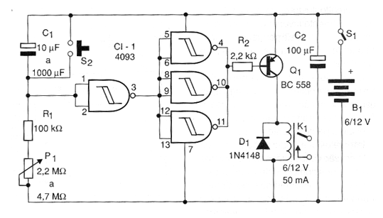
Another version of timer circuit is shown in the figure. In this circuit, when the power is established, the timing set in P1 starts. At the end of the timing the oscillator made around the second port of the 4093 triggers producing a continuous tone whose frequency basically depends on C2.
The pitch frequency produced is set to P2. The signal from this oscillator is digitally amplified by the other two ports of 4093 and applied to the piezoelectric transducer. To reset the circuit, simply press S2 for a moment. Timings can exceed one hour with the recommended maximum component values. In standby condition the alarm consumption is extremely low, which ensures excellent battery life if used as a power source.
Material list
CI-1 - 4093 - CMOS integrated circuit
R1 - 100 k ohm x 1/8 W - resistor - brown, black, yellow
R2 - 10 k ohm x 1/8 W - resistor - brown, black, orange
P1 - 2.2 to 4.7 M ohm - lin or log potentiometer
P2 - 100 k ohm - potentiometer or trimpot
C1 - 10 uF at 1000 uF x 12 V - electrolytic capacitor
C2 - 22 nF - polyester or ceramic capacitor
C3 - 100 uF x 12 V - electrolytic capacitor
S1 - Single switch
S2 - Pressure switch NA
B1 - 6 or 9 V - 4 batteries or battery
X1 - Piezoelectric transducer
Several:
Printed circuit board, battery holder or battery connector, button for potentiometer, wires, solder, etc.


