
To follow the rhythm of a song, to determine the beat of movements in a dance or gymnastics, or simply to time fast operations, a device called a metronome is used.
We describe, in this article, the assembly of a simple metronome that serves music students, gymnasts and even runners.
The proposed circuit produces good-sounding clicks on a constant-pitch speaker that can be adjusted from one beat every 3 or 4 seconds to more than 10 beats per second.
The circuit power can be supplied with voltages from 3 to 6 V (depending on the desired volume) and all components are common. There are even some components that can be taken advantage of out of use devices such as the speaker, potentiometer, etc.
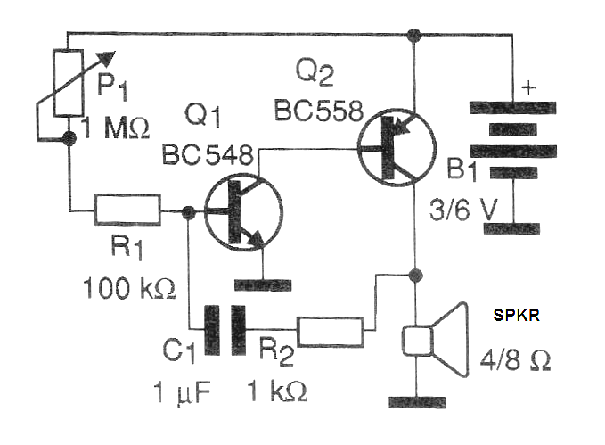
How it works: In an oscillator, part of the output signal is applied to the input in a process called feedback. It is the feedback given by C1 and R2 that determines, together with the polarization, given by R1 and P1, the frequency of the oscillations.
With a capacitor of 1 uF (electrolytic or polyester) we have a low range of frequencies or pulses, as required for a metronome.
The two transistors, one NPN and another PNP, provide amplification of the signal and thus maintain the oscillations. In Figure 1 we have the complete diagram of the low frequency oscillator that forms the metronome.
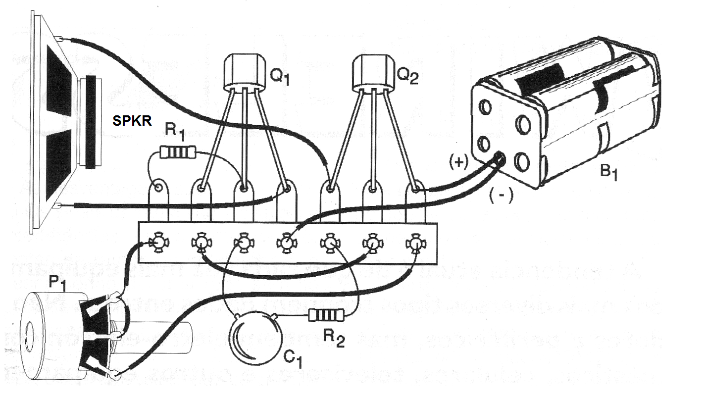
Assembly can be done on a terminal bridge as shown in Figure 2.
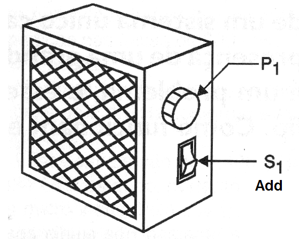
For P1 we can use both a trimpot and a potentiometer and values between 1 and 4.7 M ohms are allowed. Of course, the use of a potentiometer facilitates assembly in a box, as suggested in Figure 3, with a simple speed adjustment.
The resistors are 1/8 W or larger and the speaker can be of any size with either 4 or 8 ohms. A scale on the potentiometer, made with the aid of a common chronometer or even a "real" metronome as standard, will help a lot in the use of the device.
To test the metronome, simply place the batteries in the holder and press S1. The loudspeaker should emit interval pulses which will be set at speed through P1.
If you want to change the speed range, just replace the capacitor C1. Values between 220 nF and 10 uF can be experienced without problems.
For higher power Q2 can be exchanged for a BD135, built on a small heat radiator and the circuit powered by a higher voltage, 9 or 12 V.
MATERIAL LIST
Semiconductors:
Q1 - BC548 or equivalent - NPN transistor
Q2 - BC558 or equivalent - PNP transistor
Resistors: (1/8 W, 5%)
R1 - 100 k ohms - brown, black, yellow
R2 - 1 k ohms - brown, black, red
P1 - 1 M ohms at 4.7 M ohms - potentiometer or trimpot
Capacitors:
C1 - 1 uF - polyester or electrolytic
Miscellaneous:
SPKR - 4 or 8 ohms - speaker of any size
B1 - 3 or 6 V - 2 or 4 small batteries (or power supply for the higher power version)
Assembly box, terminal bridge, battery holder, button for the potentiometer, wires, welder, etc.


