
This circuit helps to increase the intensity of signals picked up by an antenna before being applied to the receiver. It works well in the frequency range from 200 kHz to 30 MHz, which means that it is for the wave and medium and short range but not for TV and FM.
The power consumption of this amplifier is extremely low, which means the battery life will be very long. The signals are applied to the base of the transistor and removed from its collector for application to the antenna input of the receiver. Earthing is very important.
Signals of the shortwave band, in particular, will be well amplified, thus facilitating the listening of weak or distant stations.
The transistor used is RF as the BF494 or equivalent.
Assembly
In figure 1 we have the complete diagram of the apparatus and in figure 2 its assembly realized in a terminal strip.
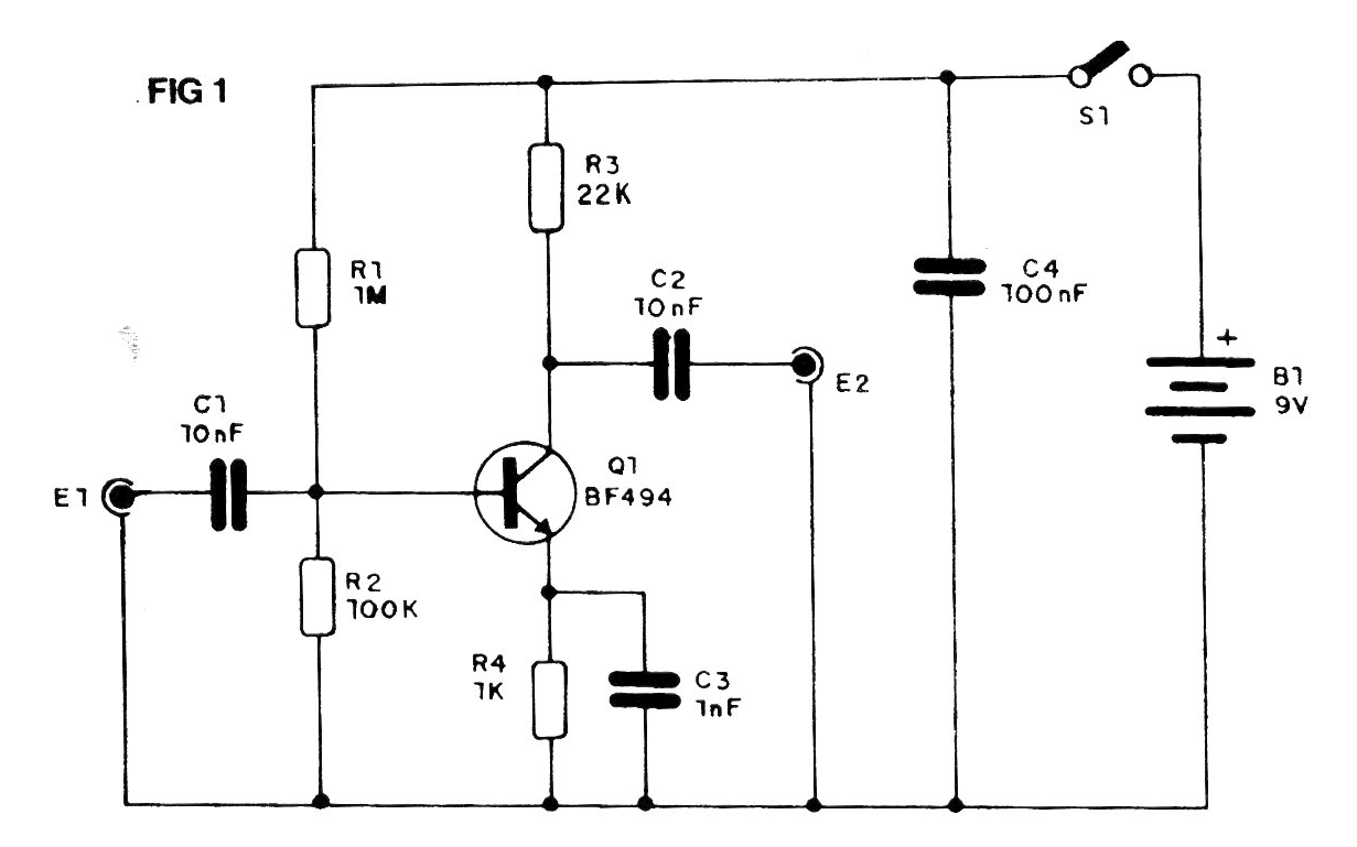
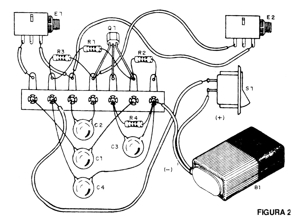
The appliance can be installed in a closed box for ease of use. The resistors are 1/8 or ¼ W and the capacitors are ceramic.
In Figure 3 we have two ways to connect to the receiver.
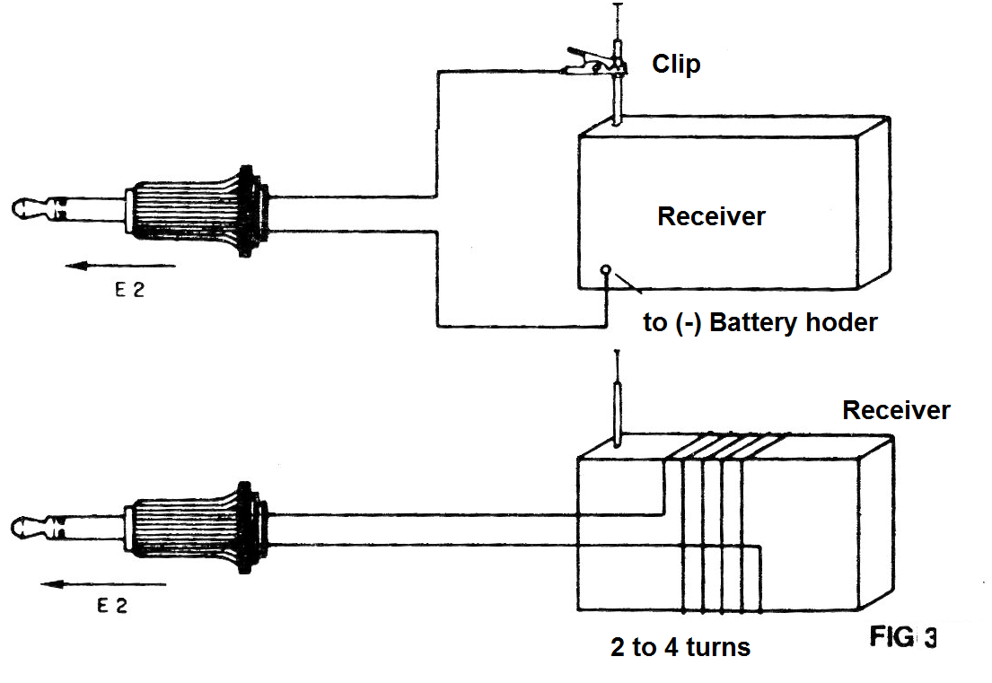
The first is for receivers with an antenna input. In the second case, we make an irradiation frame antenna consisting simply of a few turns (2 to 4) of common wire around the receiver.
The external antenna must be at least 5 meters long and grounding is indispensable.
If you do not get amplification when you turn it on, reverse the connections from the plug to the antenna.
Material list
Q1 - BF494 or equivalent - RF NPN transistor
C1, C2-10 nF- ceramic capacitor
C3 - 1 nF - ceramic capacitor
C4 - 100 nF - ceramic capacitor
R1 - 1 M ohm - resistor (brown, black, green)
R2 - 100 k ohm - resistor (brown, black, yellow)
R3 - 22 k ohm - resistor (red, red, orange)
R3 - 1k ohm x 1/8 W- resistor (brown, black, red)
B1 - 9 V - battery
S1 – Single on/off switch
Miscellaneous:
Battery connector, terminal bridge, input and output jacks, mounting box, wires, solder, etc.


