
A rheostat is a device that allows the control the intensity of the current that circulates in any circuit. This circuit can be a lamp, in which case we will have control of its brightness, an engine, in which case we will have control of its speed or a solenoid, in which case we will have control of its force. The rheostat we describe is electronic for DC and low voltage circuits, with great advantages over common types.
What happens is that a common rheostat operates as a series resistor that varies according to the current that must flow through the load. The result is that, for intense currents, the rheostat heats up, wasting energy in the form of heat. In fact, a common potentiometer can be used, but even with low currents it can get very hot.
With this rheostat we can control the speed of small motors, brightness of lamps up to 12 V with currents up to 1 A or even a little more.
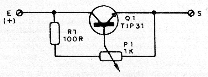
In figure 1 we have the rather simple circuit Instead of the TIP31 power transistors that are capable of controlling currents of 1 A or more like the TIP41 or even 2N3055 can be used.
In figure 2 we have the aspect of the assembly on a terminal strip.
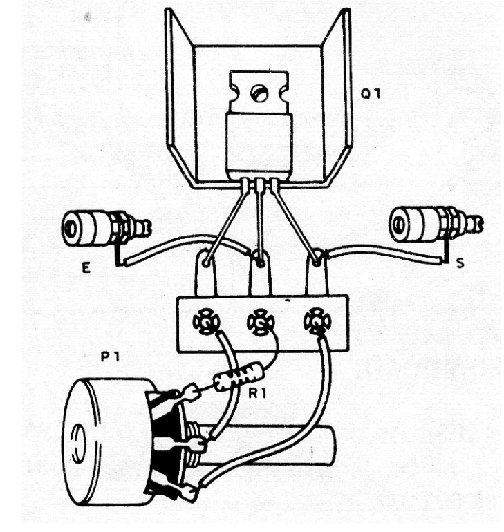
Transistor Q1 must be equipped with a heat radiator. This radiator consists of a U-folded metal plate, as well as a commercially available metal plate.
For input and output we have two terminals, but claw wires can be used. The potentiometer should be 1 k, preferably of wire, for greater dissipation. The set can be installed in a box.
To use it, simply insert between the power supply and the load, as shown in figure 3.
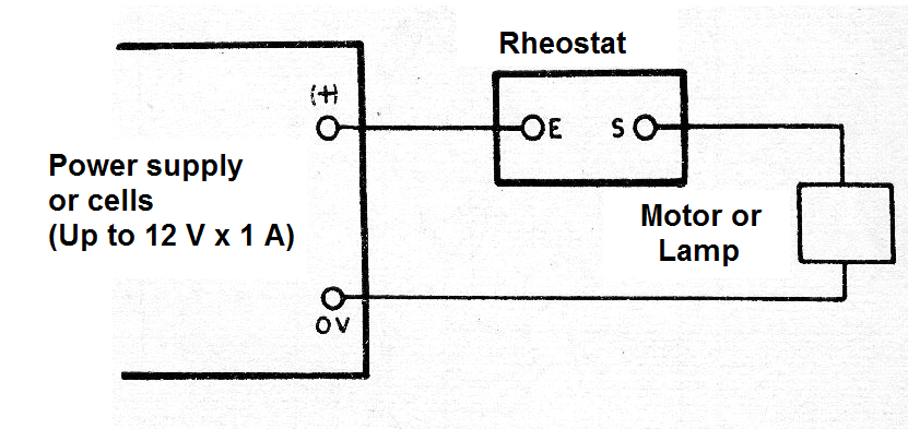
Moving the shaft of P1 there must be a variation of the current in the load. In the case of a lamp we will have a change in its brightness.
Material list
Q1- TIP31 or equivalent - NPN power transistor
P1 - 1 k - wire potentiometer
R1- 100 ohmsx 1 W - resistor - brown, black, brown
E, S - insulated terminals
Miscellaneous: heat radiator for Q1, wires, terminal strip, solder, etc.


