
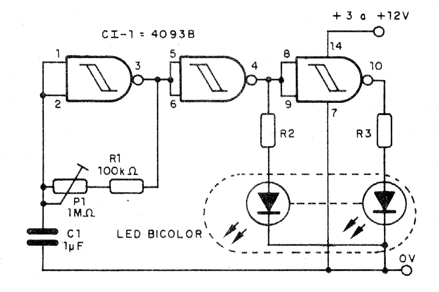
This circuit causes a bicolor LED or two different color LEDs to flash alternately at a speed that is set at the trimpot or potentiometer P1. R2 and R3 determine the intensity of the flashes, and can be between 220 ohms for 3 V up to 1.5 k for 15 V power.
The circuit can be used in decoration, in a false alarm, as an alert system and in toys. The consumption is low which makes possible it is powered by batteries or a battery. In Figure 1, we have the complete diagram of the Flasher with the integrated circuit 4093.
Assembly can be done on the basis of a small printed circuit board, as shown in Figure 2. To be used in electronic classes, the assembly can be done in a breadboard.
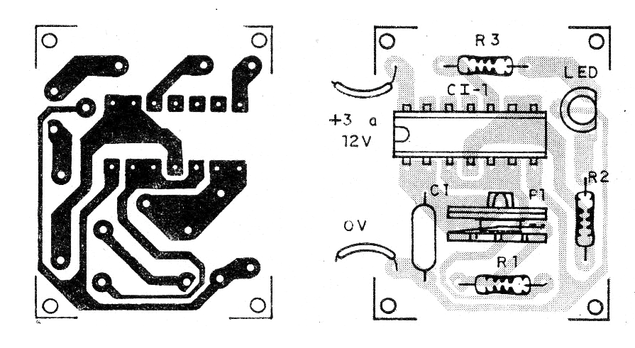
The bicolor LED is of the common cathode type, but two independent LEDs can be used.
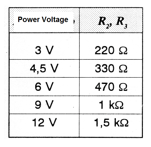
R2 and R3 depend on the power, as shown in the table below.
Material list
CI-1 - 4093 - CMOS integrated circuit
LED1 - Two-color LED or two different color LEDs
R1- 100 k ohms x 1/8 W - resistor - brown, black, yellow
R2, R3 - 220 ohms at 1,5 k - see text - resistor according to the supply voltage
P1 - 1 M ohms - trimpot
C1 - 1 uF - electrolytic capacitor or polyester
Miscellaneous: printed circuit board, wires, solder, etc.


