
When we learn to play a musical instrument, when we do gymnastics or even sing, it is essential to keep up the rythm. For this to be done in a precise way, one has the metronome feature.
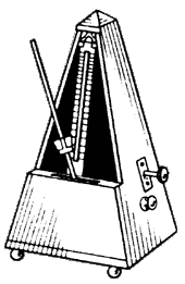
The most common type of metronome, much used in music schools, is the mechanic in which we have a rod that swings at a controlled speed, producing at the same time a tick that serves as a reference of time, as shown in figure 1.
The electronic version we describe produces ticking, with good volume on a small speaker, and can both work with ordinary batteries and with a power supply.
The clicks speeds and therefore the rhythm can be adjusted at will in a potentiometer, which facilitates its use.
For the battery-powered version we can mount the speaker with all the other components in a small speaker that will be easily transported anywhere.
In figure 2 we have the complete diagram of the metronome.

In Figure 3 we have the arrangement of the components on a printed circuit board.
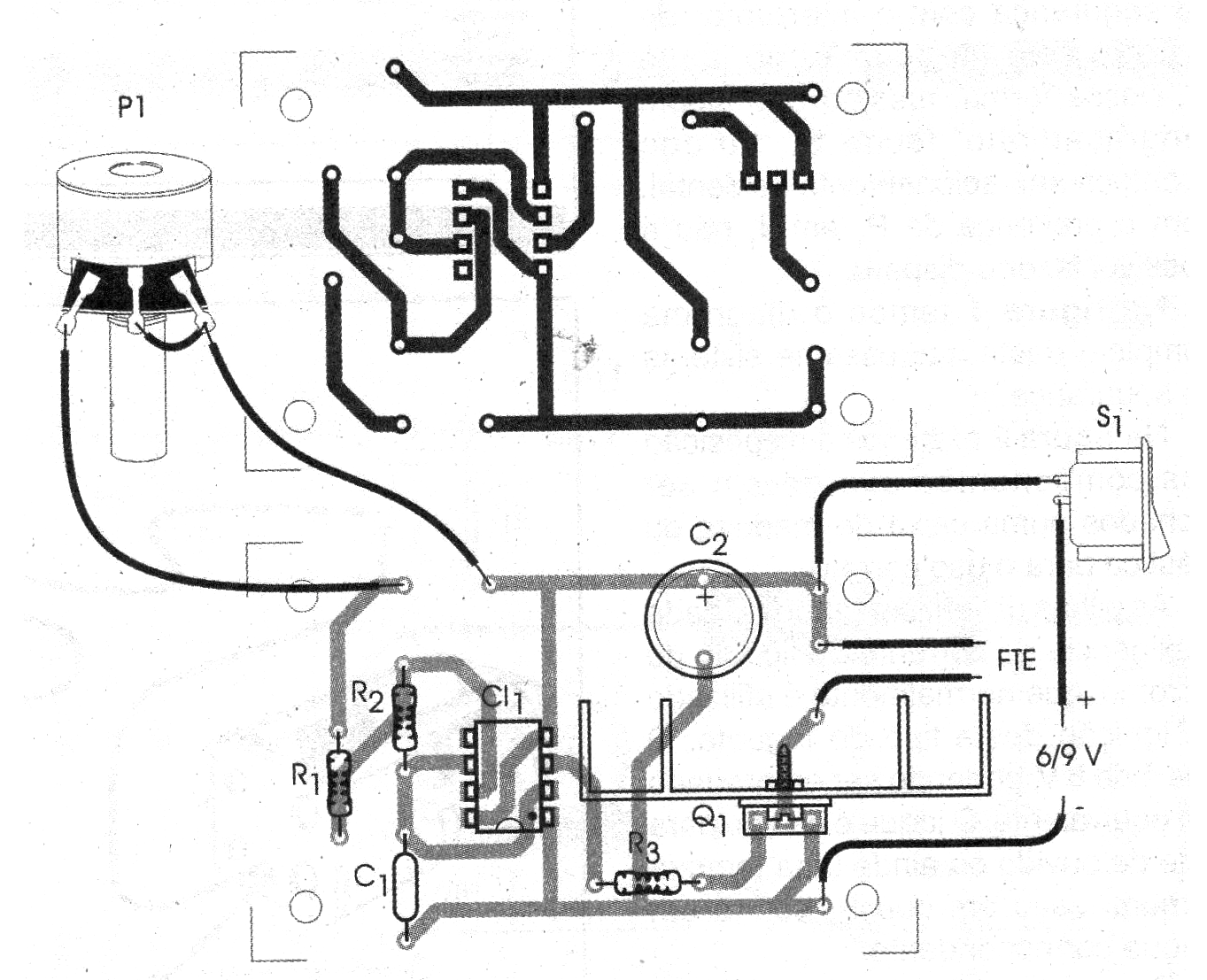
We suggest that the integrated circuit be installed in a socket and that the transistor has a small heat radiator. This radiator is nothing more than a simple 2 x 3 cm metal plate screwed into the body of the component, taking advantage of the existing hole for this purpose.
The loudspeaker must be at least 10 cm high for its impedance to be between 4 and 8 ohms. The transistor accepts equivalents such as BD137 or TIP31, but its terminals are arranged differently and must be reversed on the board.
For power supplywe suggest the use of medium cells in number of 4 or 6 since the consumption of the unit is something high. A 6 to 9 V power supply with at least 500 mA can also be used.
The potentiometer can be lin or log and possibly include the main switch S1.
To test the device just switch it on and set P1 so that the clicks
Occur at the desired frequency. To change the operating range simply change C1. This component can have values between 1 and 10 uF.
PARTS LIST
Semiconductors:
CI-1 - 555 - integrated circuit
Q1 - TIP31 or equivalent - NPN power transistor
Resistors: (1/8 W, 5%)
R1 - 22 k ohms - red, red, orange
R2, R3 - 10 k ohms - brown, black, orange
P1 - 1 M ohms - potentiometer
Capacitors:
C1 - 2.2 uF / 16 V - electrolytic
C2 - 100 uF / 16 V - electrolytic
Miscellaneous:
FTE - 4 or 8 ohms x 10 cm - speaker
S1 - Single switch
B1 - 6 or 9 V - batteries or power supply of at least 500 mA
Printed circuit board, battery holder or source, mounting box, wires, solder, heat radiator for Q1, potentiometer button, etc.


