
We show in this circuit how to obtain the locking effect for a common relay.
This effect consists of the following: When energizing the coil of a relay, it closes its contacts only while running.
When the current is cut off the relay opens its contacts.
If we want to have the relay closed after the current is cut off, ie if we want to lock the relay after it is activated, we need a special circuit.
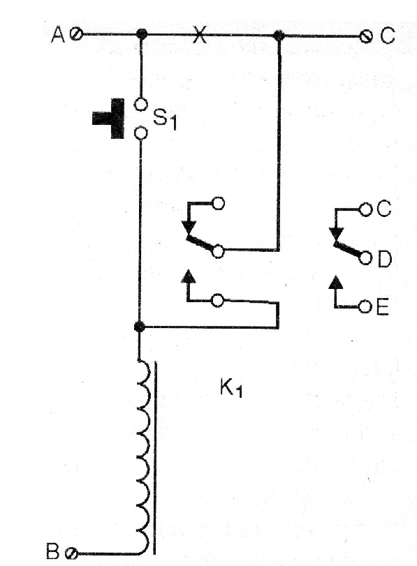
The circuit we describe takes advantage of the NO contacts of a reversible two-contact relay (any type for 6 or 12 V is suitable for this application).
In figure 1 we have the complete diagram of the relay with latch.
In figure 2 we have the actual appearance of the components in their connection to form this circuit.
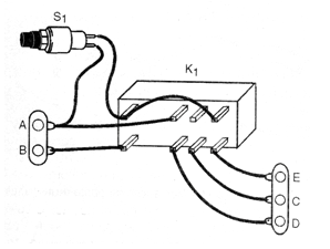
In this basic circuit we power the relay between A and B, where we apply a voltage of 6 or 12 V depending on the type of relay used.
When we press S1 the relay closes its contacts and locks.
Even after releasing S1 it remains with the contacts closed.
To disarm the relay, you must cut off the power for an instant.
An alteration option for the circuit to be able to operate with a voltage pulse is made as follows:
We eliminate S1. The input command pulse that must have the relay operating voltage is applied to C.
We connect point A to the circuit power supply positive.
A protection diode between A and pulse input may be required depending on the application.
When we apply a C-pulse, the relay trips and feeds via A.
To disconnect the circuit, the power must be interrupted for a moment in A.
Another way to disconnect the circuit is to shorten the relay coil for an instant.
Parts List
K1 - sensitive 6 or 12 V relay - any type
S1 – Push Button NA
Miscellaneous:
Terminal bridge, wires, mounting box, solder, etc.


