
The circuit shown in figure 1 serves to demonstrate the principle of operation of an astable multivibrator.
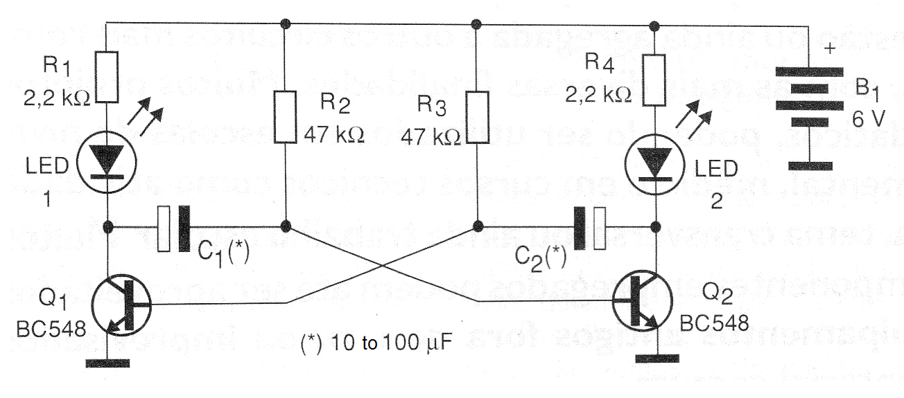
However, it can also be used for other purposes, for example as decorative element of various projects such as robots, objects, etc.
The assembly can be made based on a small terminal bridge, as shown in figure 2.

The blinking frequency is given by the capacitor values, which can be changed over a wide range of values. Capacitors from 10 to 100 uF can be tried and the higher the value of this component, the slower the blinks.
The power supply to the circuit can be made with voltages from 6 to 9 V and its consumption is very low, allowing the use of batteries or battery. The LEDs can be of different colors.
Material list
Q1, Q2 - BC548 or equivalent - general purpose NPN transistors
LED1, LED2 - Common LEDs of any color
R1, R4 - 2.2 k ohms x 1/8 W - resistors - red, red, red
R2, R3 - 47 k ohms x 1/8 W - resistors - yellow, violet, orange
C1, C2-10 at 100 uF x 12 V - electrolytic capacitors
B1 - 6 or 9 V - 4 batteries or battery
Miscellaneous:
Terminal bridge, battery holder, wires, solder, etc.


