
This simple circuit can be used to boost the signal from sources that are not able to excite your amplifier, the input of your PC, such as microphones of low and medium impedance, pickups, pickups of guitar and guitar, etc.
The circuit is very simple and compact and can even be installed inside the signal source and must be interleaved between the signal source and the amplifier itself.
The power can be supplied with voltages from 6 to 9 V from ordinary batteries or from a battery. As the required current is very low, the durability of batteries will be quite large.
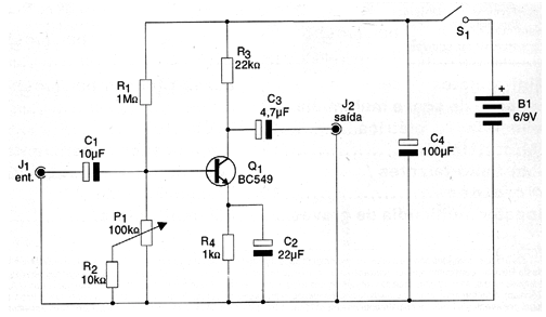
The output signal level depends on the level of the input signal and the amplification. In this case, this amplification is of the order of 50 times, but can be altered by changing the resistor R1 and also the setting of P1.
This P1 potentiometer (or trimpot) just allows the gain of the circuit to be adjusted with the signal source in order to obtain an undistorted output capable of driving the external amplifier.
In figure 1 we have the complete diagram of this simple audio preamplifier.
In figure 2 we have a suggestion for the arrangement of the components on a printed circuit board.
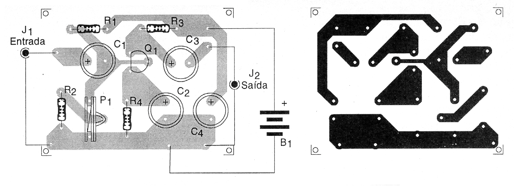
Of course, savvy readers who want a more compact assembly can use a printed circuit board, remembering that for stereo signal sources and stereo amplifiers we will need a preamplifier of this for each channel.
The connections should be short so that there is no hum, and a metal box attached to the source negative should be used to provide shielding.
The BC549 transistor provides higher gain and lower noise levels, but in common applications BC548 and even BC547 can be used without problems.
The resistors are all 1/8 W or more and the electrolytic capacitors must have minimum working voltages listed in the material list.
To test the unit simply connect it to the AUX input of any amplifier and inject a signal into its input, adjusting P1 to obtain the best level of output without distortion.
Parts List
Semiconductors:
Q1 - BC549 or equivalent - low noise NPN transistor
Resistors: (1/8 W, 5%)
R1 - 1 M ohms - brown, black, green
R2 - 10 k ohms - brown, black, orange
R3 - 22 k ohms - red, red, orange
R4 - 1k ohms - brown, black, red
P1 - 100 k ohms - trimpot or potentiometer
Capacitors:
C1 - 10 uF / 6 V - electrolytic
C2 - 22 uF / 12 V - electrolytic
C3 - 4.7 uF / 12 V - electrolytic
C4 - 100 uF / 12 V - electrolytic
Miscellaneous:
S1 – On/Off switch
B1 - 6 or 9V - 4 batteries or battery
J1, J2 - input and output jacks or plugs
Terminal strip, mounting box, shielded wires, potentiometer button, battery connector or battery holder, wires, solder, etc.


