
This circuit blocks noise and interference which propagates through the power grid. It must be inserted between the interfering device and the socket or between the interfered device and the socket. Of course, the circuit does not block noises and interferences which propagate through space.
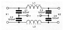
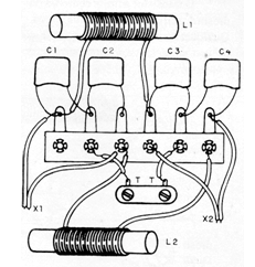
The coils consist of 20 and 40 turns of wire 20 or thicker, depending on the power of the interlayer, wound on a ferrite rod 5 to 15 cm in length. The assembly should be located inside a properly grounded metal housing (T).
The capacitors must be of polyester with at least 200 V of working voltage if the network is 110 V and at least 400 V if the network is 220 V. In Figure 1, we have the complete diagram of the filter.
Material list
L1, L2 - Coils, see text
C1, C2, C3, C4 - 100 nF - polyester capacitors - see text
X1, X2 - Sockets or plug and socket
Miscellaneous: box for mounting, wires, solder, etc.


