
Bicycle dynamos consist of an excellent source of alternative energy when coupled to the most diverse mechanical systems. We can connect them to water wheels, wind generators and other mechanical systems capable of supplying energy for their movement.
However, one of the problems of the common dynamos is that their output voltage is not regulated varying according to speed, between 0 and more than 15 V, depending on the type.
For powering any type of electronic equipment, an excess voltage or unstable voltage is dangerous and may cause it to burn.
So our simple design consists of a voltage regulator for dynamos, able to work with currents up to 1 A and provide a fixed voltage of 6 V, when the input varies between 8 and 15 V. With the use of other integrated circuits we can have different output voltages.
The complete circuit of the integrated dynamo stabilizer for dynamos is shown in figure 1.
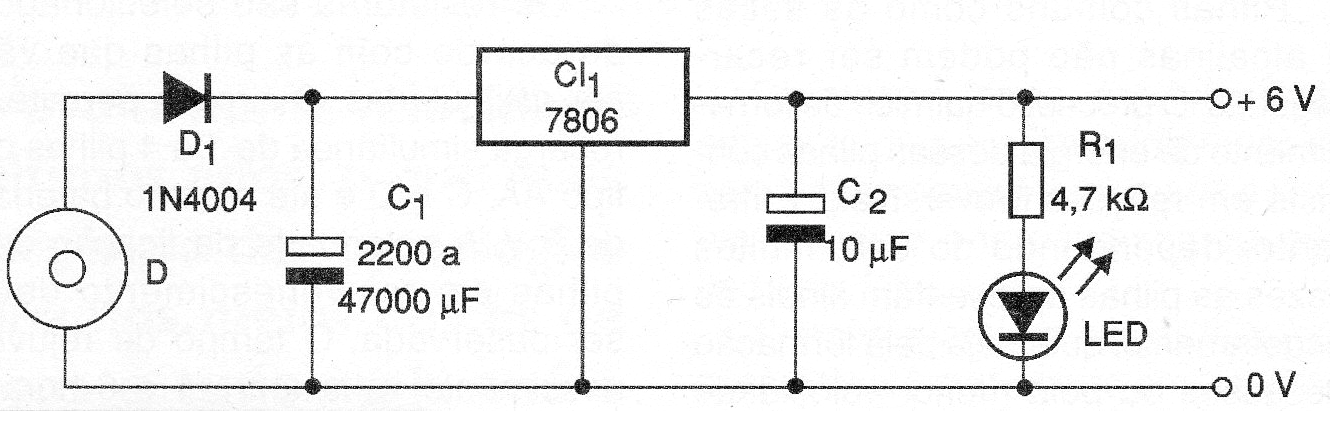
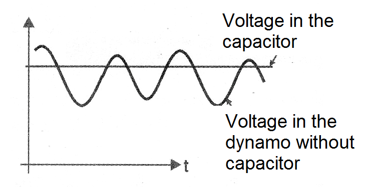
The integrated circuit should be mounted on a heat radiator and C1 is a capacitor which serves as an energy reservoir in order to eliminate the velocity oscillations of the dynamo, as shown in the graph of figure 2.
Note that the dynamo has a correct direction of rotation to provide the voltage with the polarity required to power the circuit. Also note that we need at least 2 V above the output voltage of the regulator so that the integrated circuit works properly in its function.
Input capacitors from 2 200 uF to 47 000 uF can be used. The larger, the better the stability of the output voltage, when in front of large dynamo spin oscillations.
We also note that small electric motors with permanent magnets also function as dynamos and can supply power when coupled to a rotating system. The power supplied will depend on the motor as well as its output voltage.
In figure 3 we have the final appearance of the assembly.
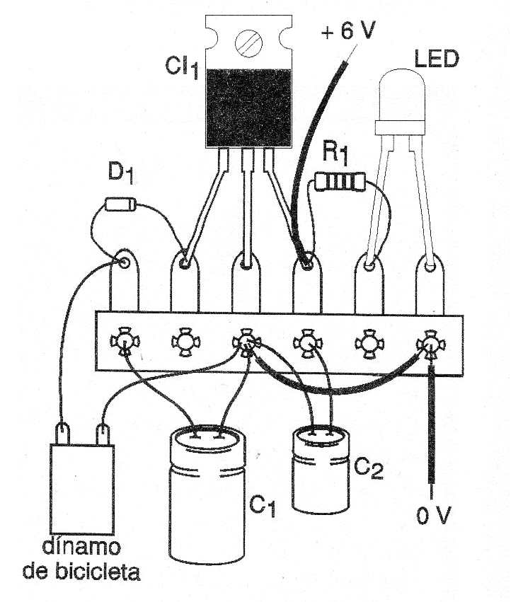
Test by measuring the output voltage and any oscillations before connecting any electronic equipment sensitive to this generator.
Material list
D - common bicycle dynamo or DC motor
D1 - 1N4004 or equivalent - silicon diode
C1 - 2 200 uF to 47 000 uF x 35 V - electrolytic capacitor
CI-1 - 7806 (or other depending on the output voltage) - integrated voltage regulator circuit
C2 - 10 uF x 12 V - electrolytic capacitor
R1 -4.7 k ohms x 1/8 W - resistor - yellow, violet, red - optional
LED - common red LED - optional
Miscellaneous:
Wires, mechanical system, bridge of terminals, solder, heatsink for the integrated circuit, etc.


