
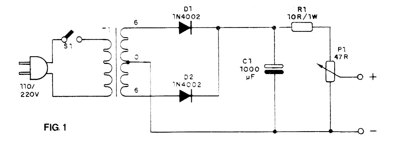
This circuit has the purpose of powering devices and circuits from 0 to 6 V with currents up to 250 mA, without problems. The output voltage adjustment is done by a wire potentiometer (do not use of another type) and the filtration obtained through a capacitor of 1 000 uF. The circuit has no automatic adjustment.
We can power the smaller power projects, smaller radios and calculators and other less critical devices.
The transformer must have primary winding according to the power grid (110 V, 127 or 220 V) and secondary winding of 6 + 6 V with a current between 100 and 250 mA.
The working voltage of the electrolytic capacitor must be 12 V or more and the resistor R1 is d 1 or 2 W. The diodes must have a working voltage of at least 50 V.
Assembly
In figure 1 we have the complete diagram of the power supply and in figure 2 its assembly on terminal strip. It is recommended to use a box for mounting.

The output terminals must be red (+) and black (-) for polarity identification. The S1 switch is a simple switch to turn the power on and off.
Material list
D1, D2 - 1N4002 or equivalent - silicon diodes
C1- 1000 uF - electrolytic capacitor (12 V or 16 V)
R1- 10 ohm x 1 W - resistor
P1- 47 ohm - wire potentiometer
T1 - Transformer - see text
S1 - Single switch
Miscellaneous:
Power cable, mounting box, terminal strip, potentiometer knob, wires, solder, etc.


