
The apparatus, in its mechanical part has a metal blade and two electromagnets wrapped in little hands. When we couple this device to an electronic circuit, the blade vibrates at a speed that depends on the characteristics of the electronic circuit.
If the vibration is slow, we have a little metronome or immitation of the ticking of a mechanical clock. If the vibration is rapid we will have the sound of a horn or bell.
The basic purpose of the project can be both recreational and also to demonstrate the operation of the electromagnet and on a more advanced scale, the operation of an astable multivibrator.
How it works
The electromechanical part consists of two small electromagnets wrapped in common nails. Between them is fixed a metal blade (piece of tin) that can vibrate with certain facility. In the resting condition, the blade does not rest on any of the electromagnets.
When we alternately feed one or another electromagnet, the blade is drawn into vibration.
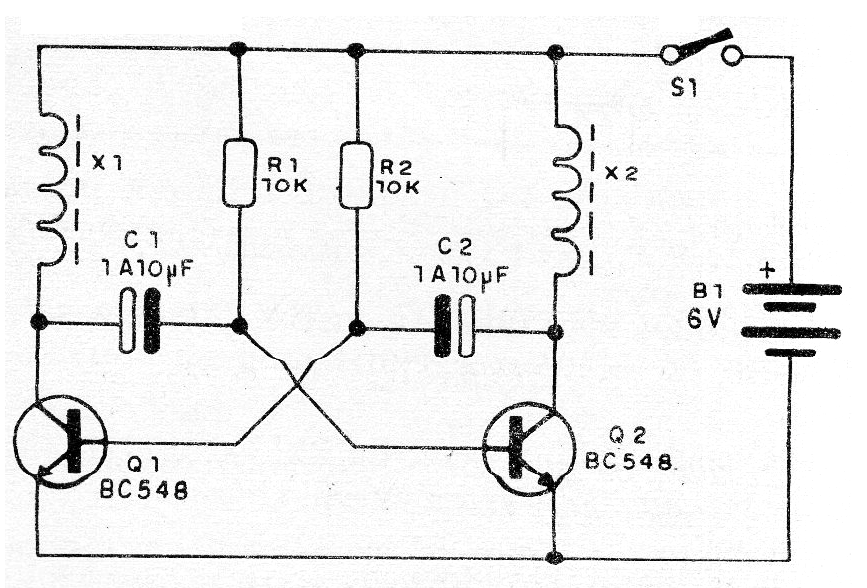
To activate the electromagnets we use an electronic circuit that consists of an astable multivibrator. In this circuit we have two transistors (Q1 and Q2) that function as electronic switches, turning on and off the current of the electromagnets, at a speed that depends on C1 and C2.
For small capacitors (low values) we have loads and fast discharges, which make the state change of the transistors very fast. Under these conditions the blade vibrates. In the condition where we place larger capacitors, the state change is slow and the blade changes state by moving from one side to another with a click.
When mounting this unit, capacitor values can be tested over a wide range of values.
Circuit power is supplied by standard batteries or 6 V sources with a current of at least 200 mA.
Assembly
In figure 1 we have the complete diagram of the apparatus
In figure 2 we have the arrangement of the components in the actual assembly.
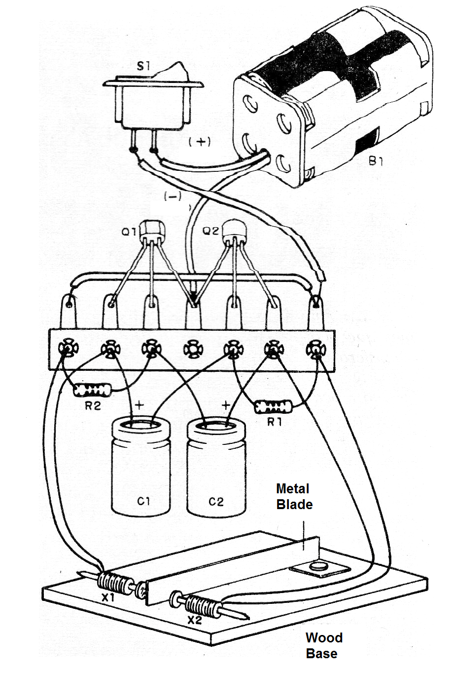
The two nails can be fixed in small stumps in the lateral stop. In each nail we rolled 200 to 500 rounds of fine enameled wire. The tips should be scraped at the welding points.
The components are soldered on the terminal bridge. The polarity of the capacitors, the position of each transistor and the polarity of the batteries must be observed.
Use
Just turn on the power and observe the movement of the blade, making any adjustments to get a better vibe.
Material list
Q1, Q2 - BC548 or equivalent - NPN transistors
X1, X2- electromagnets- see text
S1- Single switch (optional)
C1, C1-1 uF to 100 uF- electrolytic capacitors
R1, R2- 10 k ohm x 1/8 W resistors - brown, black, orange
B1- 6 V - 4 batteries
Miscellaneous: terminal strip, battery support base for assembling, small nails, wires, welding etc.


