
A multivibrator is a circuit in which two transistors are constantly switching state. When one "turns on" the other "turns off’.
The speed at which this occurs depends on the capacitors and resistors connected to their bases.
In our case, the status change causes the LEDs controlled by the transistors to be switched on and off alternately.
The multivibrator circuit is given in Figure 1.
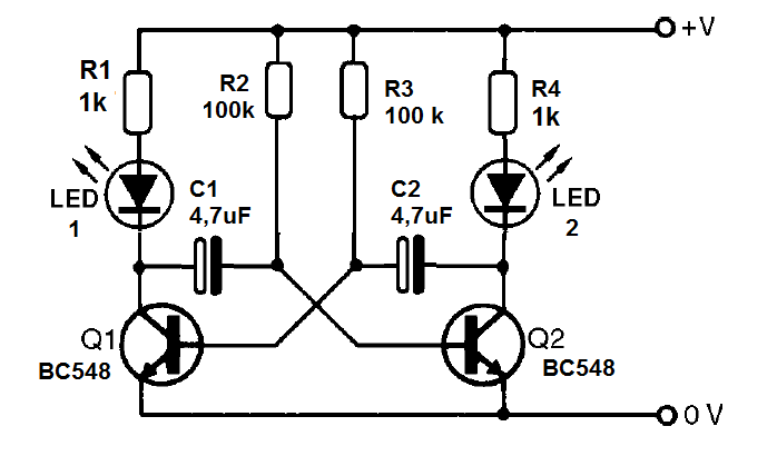
Figure 1 - The multivibrator | Clique na imagem para ampliar |
The assembly on the breadboard is shown in Figure 2.
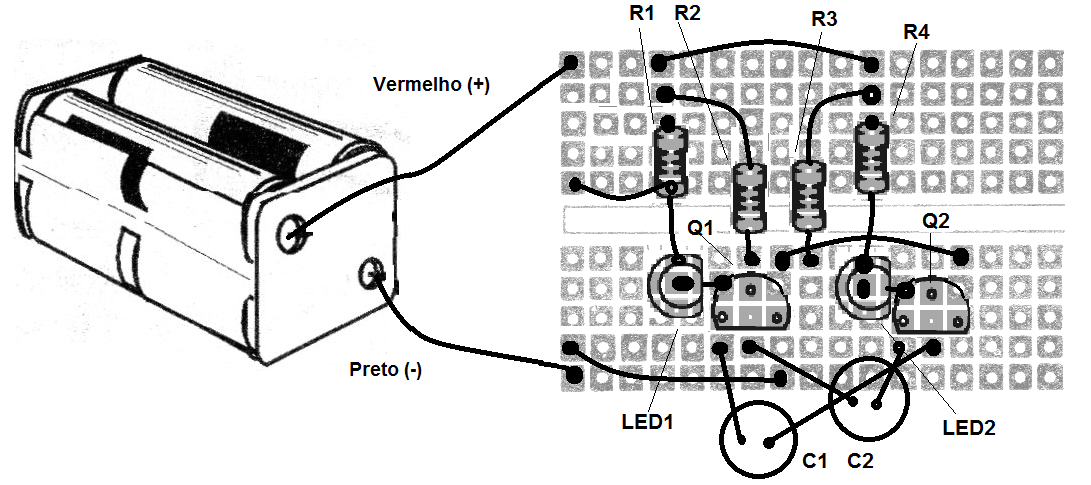
Figure 2 - Assembly on the breadboard | Clique na imagem para ampliar |
Material list
Q1, Q2 - BC548 - NPN transistors
LED1, LED2 - Common LEDs
R1, R4 - 1k ohm - resistor - brown, black, red
R2, R3- 100 k ohm - resistor - brown, black, yellow
C1, C2 - 4.7 uF at 22 uF - electrolytic capacitors
B1 - 6 V - 4 batteries
Miscellaneous:
breadboard, support of batteries, wires, etc.


