
With this circuit we can test ceramic capacitors, polyester, styroflex and other non-polarized types in the range of 1 nF to 470 nF. The status indication is audible, ie a good capacitor will cause the unit to emit a sound whose frequency depends on its value.
Larger capacitors will produce more bass sounds.
With known capacitors we can even establish the value of the capacitor under test by comparing the produced sounds.
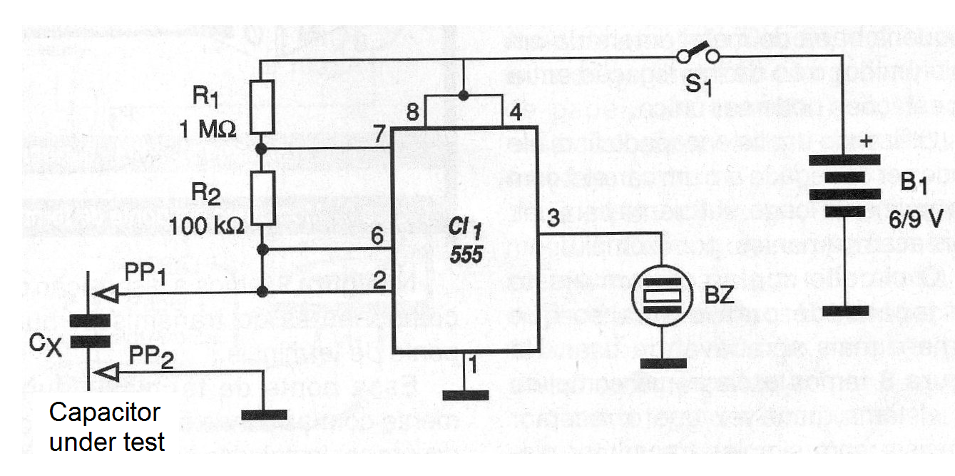
The circuit consists of a simple oscillator that depends on the capacitor in test to operate.
This circuit is based on an 555 in the astable configuration.
Power supply is formed by 4 common batteries or even a 9 V battery. The drained current is very low which guarantees great durability for the power supply.
In figure 1 we have the complete diagram of the capacitor test.
In figure 2 we have the arrangement of the components on a printed circuit board.
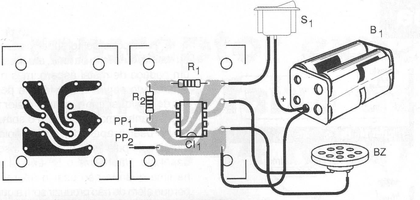
Assembly can also be done easily on protoboard.
For the integrated circuit, we suggest the use of an 8-pin DIL socket. The resistors are 1/8 W and the transducer can be either piezoelectric type or high impedance crystal.
The resistors are 1/8 W and the probes can be acquired ready or improvised with common nails.
A suitable holder with the observed polarity must be used for batteries.
The set fits in a plastic box of reduced dimensions.
Use:
Operating the test is simple: just connect a good capacitor, with a value within the indicated range, between the probes.
The larger capacitors produce interval pulses since we will have a very low frequency for the signal.
To use the device, simply push the probes into the capacitor under test. If there is sound emission, the capacitor will be in good condition.
If nothing happens then either the capacitor will be short, open, or still have value outside the range that the taster can operate.
MATERIAL LIST
Semiconductors:
CI-1 - 555 - integrated circuit
Resistors: (1/8 W, 5%)
R1 - 1 M ohms - brown, black, green
R2 - 100 k ohms - brown, black, yellow
Miscellaneous:
BZ - Ceramic transducer - see text
B1 - 6 or 9 V 0 4 batteries or battery
S1 - Single switch
PP1, PP2 - Red and black probes
Printed circuit board, battery holder, integrated socket, mounting box, wires, solder, etc.


