
This circuit generates signals in the long wavelength range from 100 kHz to 500 kHz and can be used as a base for experimental transmitters, signal generators, research apparatus and in many other applications.
The power of the circuit is low, in the order of a few tens of milliwatts, but even so, by connecting to an antenna, the signals can be picked up from a distance of a few meters with an appropriate receiver.
Signal output can be done in two ways:
A) When connecting the antenna or output to the transistor collector
B) From a second coil of 30 to 40 turns of the same wire on L1.
Circuit power can be supplied with voltages from 3 to 9 V and as the consumption is relatively low, common batteries or a battery can be used.
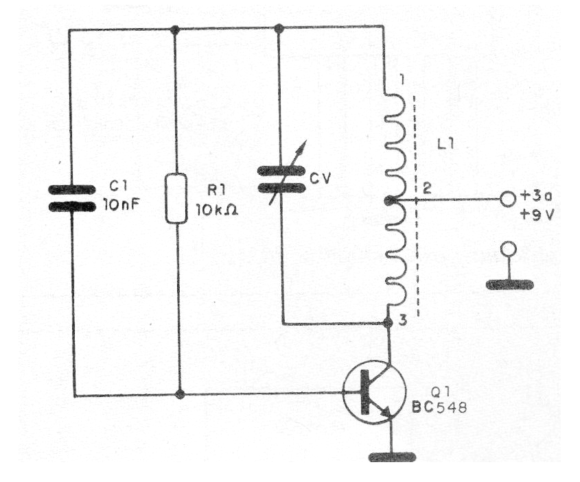
In figure 1 we have the complete diagram of the oscillator.
In figure 2 its assembly is based on a terminal strip.
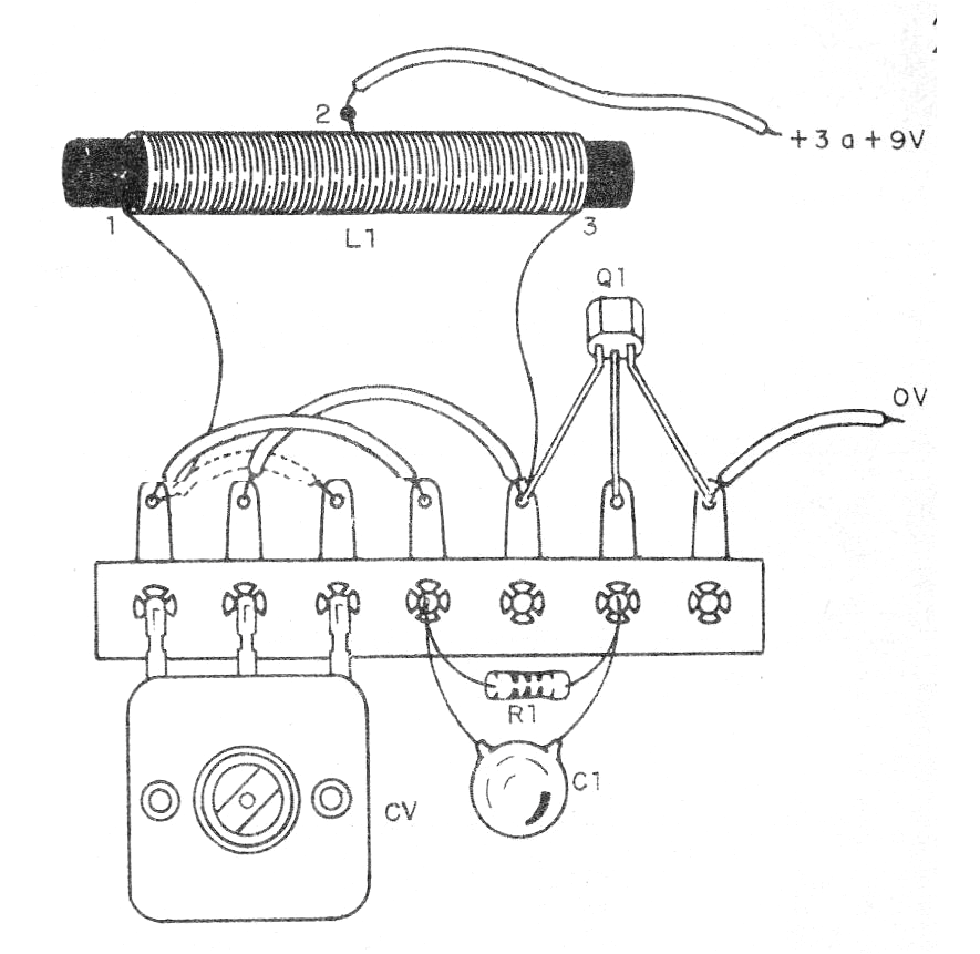
The coil L1 is formed by 200 turns of wire 28 or finer in a ferrite rod, with socket in the 50th turn. The variable capacitor can be obtained from an unused transistor AM radio. The capacitance of this component will determine the frequency range swept by the oscillator.
The transistor can be any NPN of general use or medium power like the BD135. The other components are common.
To verify the operation an AM receiver can be used, which will pick up the harmonics from this circuit, or by winding about 40 turns of wire over the coil and connecting to the lower AC range of the multimeter.
Material list:
Q1- BC548 or equivalent - general purpose NPN transistor
L1- Coil - see text
CV - Variable capacitor - see text
R1 - 10k ohm x 1/8 W- resistor - brown, black, orange
C1 - 10 nF - ceramic capacitor
Miscellaneous:
Batteries or battery, connector or battery holder, terminal bridge, ferrite rod, wires, solder, etc.


