
This circuit can be embedded in robots and other automatisms in order to indicate its operation.
The important thing about this project is that its power consumption is around 0.001 watt which means that it can stay on permanently without this meaning any sensible increase in your energy bill.
It is therefore the ideal signaling configuration for a circuit that must be permanently connected.
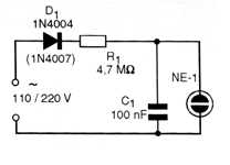
What we have is a relaxation oscillator where capacitor C1 is charged via R1 until the neon lamp voltage is reached, something around 80 volts.
When this occurs, the lamp produces a flash and the capacitor partially discharges.
When the lamp goes out we have a new charge cycle and then the trigger.
The capacitor C1, together with R1, determines the operating frequency of the circuit.
If you need to change the frequency of the circuit replace C1 and not R1.
In figure 1 we have the complete diagram of the blinker or flasher.
In figure 2 we have the arrangement of the components on a terminal bridge.
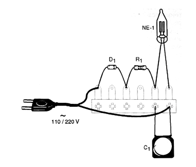
The neon lamp can be of any type with the appearance indicated in the figure.
Resistors are 1/8 W or larger.
For the 110 V (127V) grid, the diode should be 1N4004 and for the 220 V grid the 1N4007.
The entire assembly can be embedded in robots, mechanical arms, wall switches, and other places where permanent signaling of presence of tension or operation is desired.
Parts List
NE-1 - common neon lamp
D1 - 1N4004 or 1N4007 - silicon diode
R1 - 4.7 M ohms - yellow, violet, green
C1 - 100 nF / 100 V - polyester capacitor
Miscellaneous:
Terminal strip, power cable, wires, solder, etc.


