
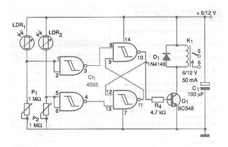
The circuit we present consists of a photoelectric control with bistable action. A light pulse on LDR2 turns on the relay and a new pulse on LDR1 turns off. The sensitivity is set in the trimpots or potentiometers P1 and P2.
The LDRs are of the ordinary round type, and can be installed in opaque tubes with lenses for greater sensitivity and directivity. The relay is of a sensitive type of 6 V or 12 V depending on the voltage used in the power supply. The coil must have a maximum drive current of 50 mA.
The connection wires to the sensors (LDRs) can be long, up to 20 meters in length. With the increase of P1 and P2 to 10 M ohms, photo-transistors can be used as sensors.
Material list
CI-1 - 4093 - CMOS integrated circuit
Q1 - BC548 or equivalent - general purpose NPN transistor
D1 - 1N4148 - general purpose diode
P1, P2 - 1 M ohm - trimpot or potentiometers
R1 - 2.2k ohm x 1/8 W - resistor - red, red, red
C1 - 1000 uF x 16 V - electrolytic capacitor
K1 - Relay - see text
LDR1, LDR2 - Round common LDRs - DSD4060 or equivalent
Several:
Solderless board or printed circuit boards, battery or source holder, wires, solder, etc.


