
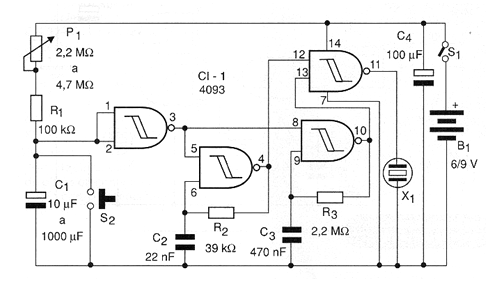
The first circuit drives a piezoelectric which will emit interval beeps whose frequency and range depend on C2 and C3. This circuit is shown in the figure using only a 4093 integrated circuit with 6 or 9 V supply.
When the circuit power is switched on, the C1 capacitor charges slowly through P1 and R1, while the circuit continues to emit interval beeps. When the capacitor load reaches enough that the input of the first port recognizes it as high, the output goes low and the two oscillator circuits formed by the following ports are disabled.
The fourth port of the integrated circuit functions as a digital buffer amplifier, directly exciting the high impedance piezoelectric transducer. The maximum time interval obtained depends on C1 and the circuit is reset by pressing for a moment S2.
One possibility of modifying this circuit consists in the activation of a relay with a power stage, in which case it will be pulsating a power charge until the end of the time. A Darlington power can also be fired for direct control of a larger load.
Material list
C I-1 - 4093 - CMOS integrated circuit
R1 - 100 k ohm x 1/8 W - resistor - brown, black, yellow
R2 - 39 k ohm x 1/8 W - orange, white, orange
R3 - 2.2 M ohm x 1/8 W - resistor - red, red, green
P1 - 2.2 M ohm at 4.7 M ohms - lin or log potentiometer
C1 - 10 to 1000 uF x 12 V - electrolytic capacitor - see text
C2-22 nF -n ceramic capacitor or polyester
C3-470 nF - polyester capacitor
C4 - 100 uF x 12 V - electrolytic capacitor
S1 - Single switch
S2 - Pressure switch NA
B1 - 6 or 9 V - 4 batteries or battery
X1 - High impedance piezoelectric transducer
Several:
Printed circuit board, battery holder or battery connector, button for potentiometer, wires, solder, etc.


