
Connected to the output of an audio amplifier or to the telephone jack of a transistor radio, this circuit triggers a relay with the external signals of a microphone, a recording or even picked up by the receiver.
Using an FM radio and a tone-modulated transmitter, we can make this circuit a low-cost remote control. There are several additional possibilities, such as alarms, sonic switches, flash firing and many other cases.
The circuit works with the audio signal that is rectified by the diode and filtered to be amplified by the transistor and to activate the relay, which in turn controls the external circuit.
Circuit power can be supplied from batteries or a source of at least 200 mA. The sensitivity setting is the volume control of the amplifier or radio used.
In figure 1 we have the complete diagram of the apparatus.
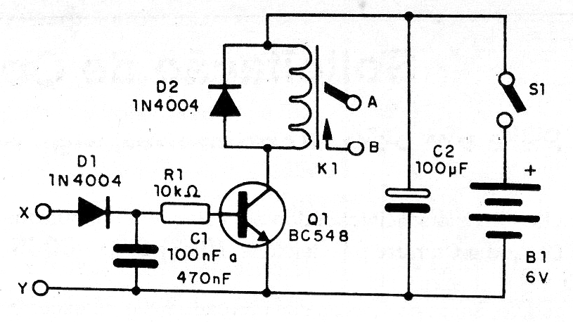
As the circuit is not critical, as well as the arrangement of the components, we can make the assembly based on a terminal strip, as shown in figure 2.
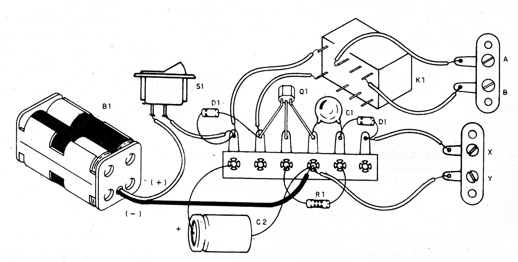
Between A and B we connect the circuit to be controlled and between X and Y we apply the audio signal that will control the circuit. To use, adjust the volume of the audio equipment until the desired sound triggers the relay. The circuit needs approximately 1 V for its drive.
Material list
Q1 - BC548 or equivalent - general purpose NPN transistor
D1, D2 - 1N4004 or equivalent - silicon diodes
K1- ML2RC1 - 6 V Relay
S1- Single switch
B1- 6 V - 4 batteries or source
R1- 10 k ohm x 1/8 W- resistor - brown, black, orange
C1- 100 to 470 uF x 6 V or more - electrolytic capacitor
C2 - 100 uF x 12 V or more - electrolytic capacitor
Miscellaneous:
Terminal bridge, battery holder or source, mounting box, 2-terminal bridges with screws, wires, solder, etc.


