
170 Points Breadboard assembly whose purpose is to learn how a Darlington configuration of two transistors works and to use it in a very sensitive sensor of touch
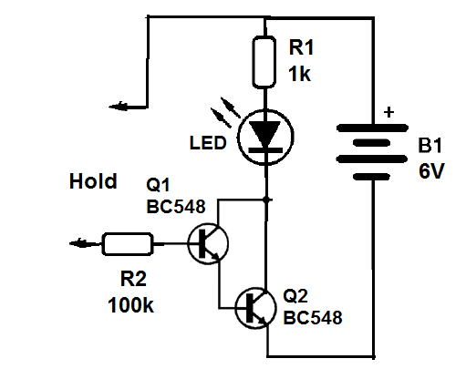
Two transistors connected in a direct coupling, so which the emitter of the first is connected to the base of the second and the interconnected collectors form a Darlington pair or stage.
The signal is applied at the base of the first transistor and drawn from the emitter of the second or common collector.
In our circuit, we will use two BC548 transistors connected as Darlington so that a very small current at the base of the first is enough to cause a much larger current in the second collector.
Thus, a tiny current which passes through the base of the first, coming from the touch of our fingers is enough to light the LED.
This circuit is much more sensitive than the project of the touch switch with a transistor, because the gain is much greater.
Assembly
In Figure 1, we have the complete circuit of the touch switch.
The assembly on the breadboard is shown in Figure 2.
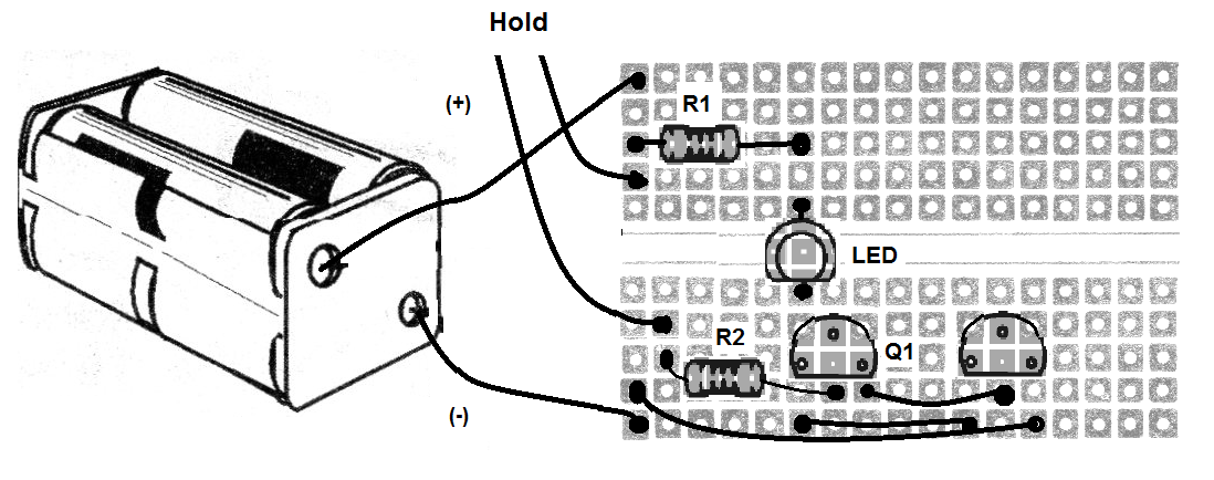
When building, carefully observe the positions of the two transistors and the LED.
Check all wiring connections carefully, taking care not to miss the interconnections of the transistors.
Material list
Q1, Q2 - BC548 - NPN transistors
LED - LED common
R1 - 1 k ohm - resistor - brown, black, red
R2- 100 k ohm - resistor - brown, black, yellow
B1 - 6 V - 4 batteries
Miscellaneous:
breadboard, battery holder, wires, etc.


