
A single unijunction transistor enables the construction of this instrument of great utility in the diagnosis of defects in audio equipment.
We have talked a lot about our signal injector articles and their usefulness in addition to always giving designs of these devices. Well, we have one more signal injector that, this time, uses an already not very common transistor, which is the unijunction transistor (UJT).
The circuit generates a signal in the audio track, but whose harmonics reach higher frequencies, including for the RF tests. The circuit has a very low consumption and can be powered by a 9 V battery.
It is a relaxation oscillator whose frequency depends on C1 and can be set at P1. The oscillator pulses are applied to a transformer for application to the external circuit. We have two pulse options for testing, depending on the selector switch. In the upper position we have negative pulses and in the lower positive pulses.
Figure 1 shows the complete diagram of the injector and in figure 2 we have its assembly on a terminal bridge.
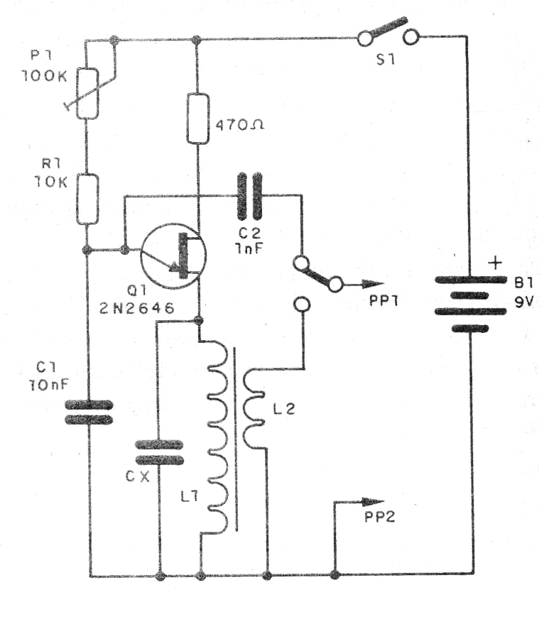
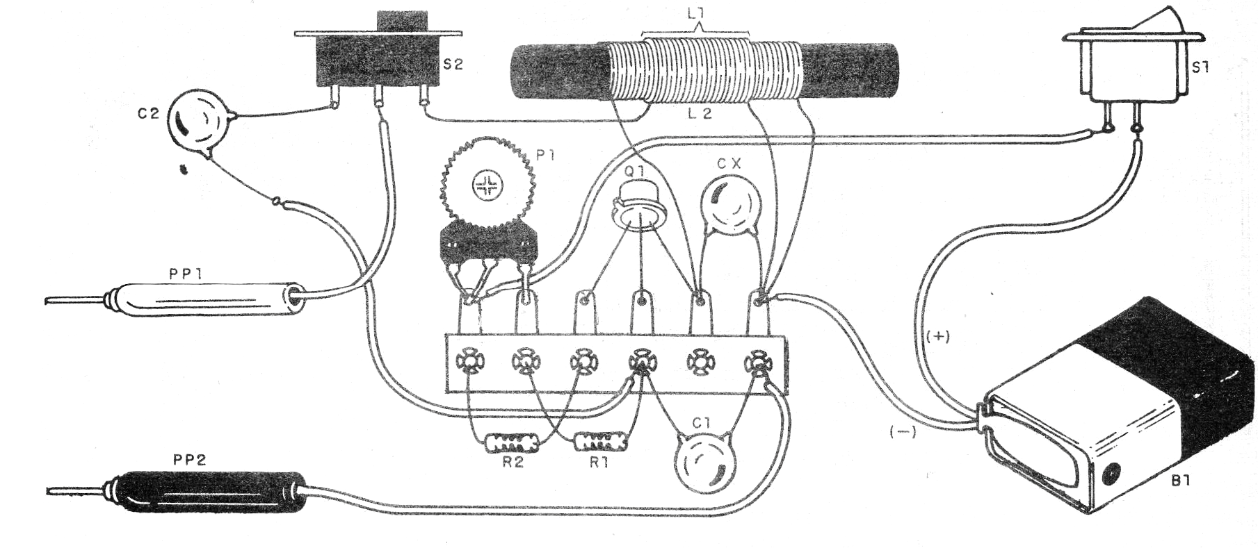
The transformer is wound on a ferrite rod with wire 32 or finer. L1 consists of 100 to 200 defio turns and L2 by 20 to 40 turns of the same wire, on L1, as shown in the figure.
The other components are all common and in place of the trimpot a potentiometer of the same value can be used. To test, simply bring the circuit closer to a nearby midrange radio and tuned to a free frequency.
Material list
Q1 - 2N2646 - unijunction transistor
P1 - 100 k - trimpot
R1 - 10k ohms x 1/8 W - resistor - brown, black, orange
E2 - 470 ohms x 1/8 W- resistor - yellow, violet, brown
L1, L2 - Coils - see text
C1- 10 nF - ceramic capacitor
Cx - capacitor between 1 nF and 10 nF - obtain experimentally
PP1, PP2 - Probes
S1 – On-Off switch
S2 – 1 pole x 2 positions switch
B1- 9 V - battery
Miscellaneous: terminal strip, battery connector, wires, solder, etc.


