
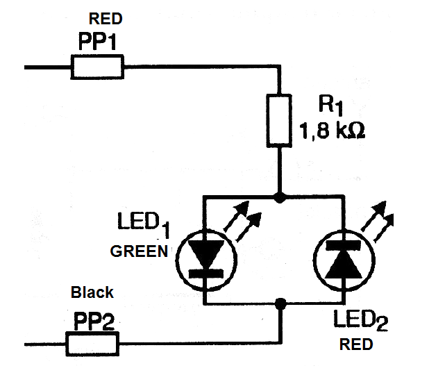
This circuit uses only 3 components and is of great use in the bench of many experimenters, students, makers, teachers and even the repair technician. With it we can know which is the positive or negative pole of a battery eliminator, power supply or circuit under repair, which can be very important for its integrity.
The only requirement for its use is that the voltage to be identified by polarity is between 2 and 12 volts, because above that the current may be excessive in the LED, putting its integrity at risk.
We have as indicators two LEDs, lighting one or the other if the voltage is continuous, depending on the polarity. If the voltage is switched on, the two LEDs light up. In figure 1 we have the complete circuit of our polarity indicator.
In figure 2 we have the arrangement of the components in a terminal strip which fits easily into a plastic box of quite modest dimensions.
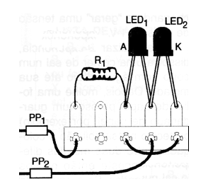
The probes should be black and red for polarity identification. The resistor can be 1/8 W or larger and the LEDs should be of different colors, preferably one red and one green.
The circuit does not require a power supply, since the voltage of the circuit in test is used for its activation.
The use of the indicator is very simple: just touch the probes at the outputs of the circuit under test. If the green LED lights up then the polarity of the tips coincides with that of the circuit: red to positive and black to negative.
If it is the red LED which lights up, then the polarity is reversed, ie the black probe, which is on the positive.
The circuit does not operate with voltages less than 2 volts because this is the minimum value that the green LED needs to light up.
MATERIAL LIST
LED1 - Common green LED
LED2 - Common red LED
R1 - 1.8k ohm or 2.2k ohm - resistor (brown, gray, red or red, red, red)
PP1, PP2 - Black and red probes
Miscellaneous:
Terminal bridge, mounting box, wires, solder, etc.


