
This is an assembly for those who are learning electronics (STEM) or need a simple circuit that causes two LEDs to blink alternately. The circuit is powered by 4 batteries or handset and uses only two transistors and some passive components.
What we have is an astable multivibrator whose frequency is basically determined by the capacitors C1 and C2. If these capacitors have small values (47 uF) the blinks will be fast and if they have higher values (220 uF or 470 uF), the blinks will be slower. In this range of values you can try the capacitors you want.
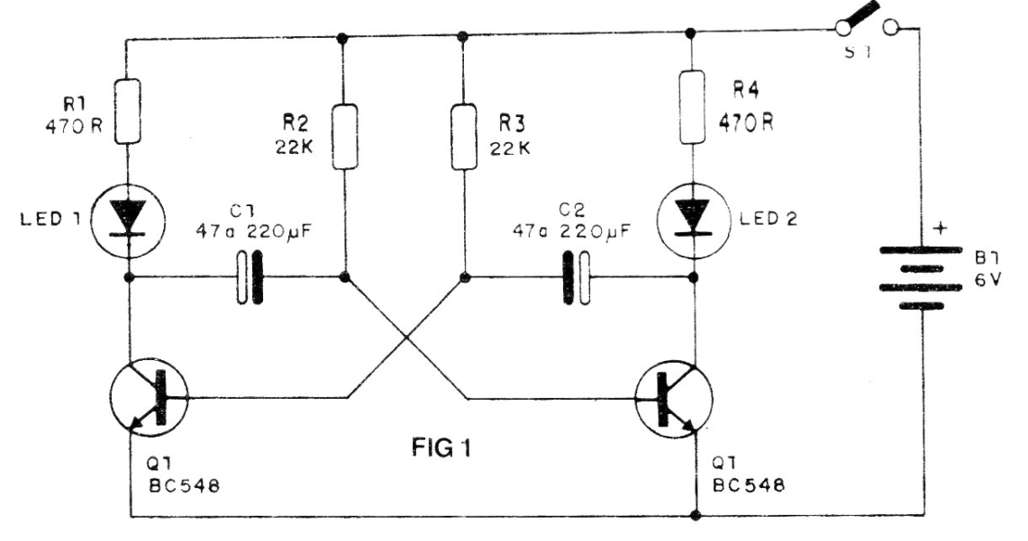
The brightness of the LEDs is given by R1 and R4, but it is not convenient to reduce these resistors to less than 470 ohms. With higher values we will have lower brightness and lower energy consumption of the batteries.
The resistors R2 and R3 are also not critical and values between 15k and 47k can be tried.
In figure 2 we have the assembly in a deterministic bridge. In this assembly it is necessary to observe the position of the transistors, polarity of the LEDs and capacitors besides the battery.
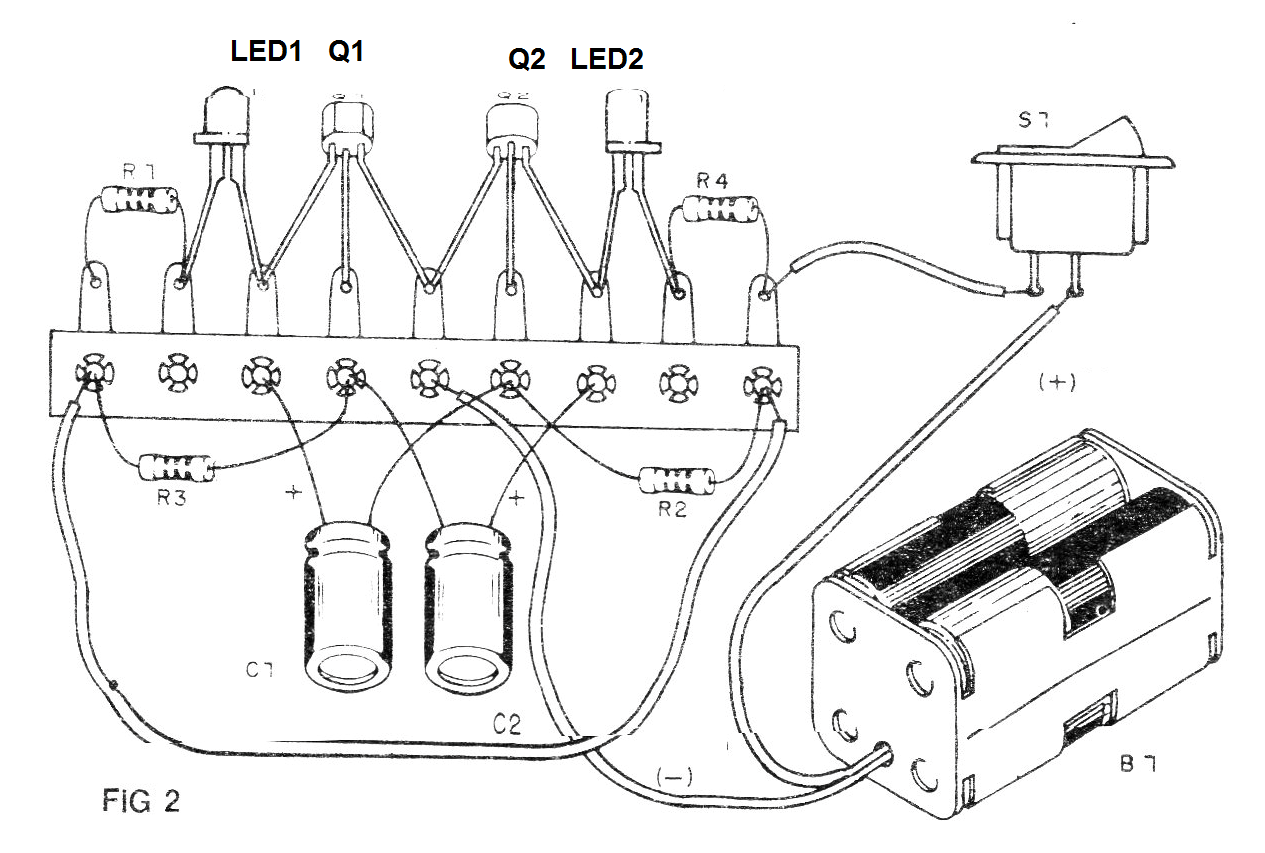
Install your flasher in a plastic case for ease of use.
Material list
Q1, Q2 - BC548 or equivalent - general purpose NPN transistor
LED1, LED2 - Common LEDs of any color.
C1, C2 - electrolytic capacitors for 6 V or more - see text
B1 - 6 V - 4 small batteries
S1 - Single switch
R1, R4 - 1k ohm - resistors (brown, black, red)
R2, R3 - 22k ohm - resistors (red, red, orange)
Miscellaneous:
Terminal strip, support for 4 small batteries, wires, mounting box, etc.


