
Most of the headphones, used in sound equipment like portable radios, walkmans and even padded older sound equipment, are of low impedance.
This means that they do not have sensitivity characteristics or proper conditions to be directly excited by the output of many transistor circuits, crystal radios, super-regenerative VHF and FM experimental receivers, etc.
If the reader likes to make experimental assemblies that require a high-impedance handset but his is low, the solution lies in the circuit assembly that we describe.
What we have is not just a circuit that turns your low-impedance handset into a high-impedance handset but also provides extra signal gain that provides great sensitivity to the handset. We actually have a booster or booster for your handset, using a good gain transistor.
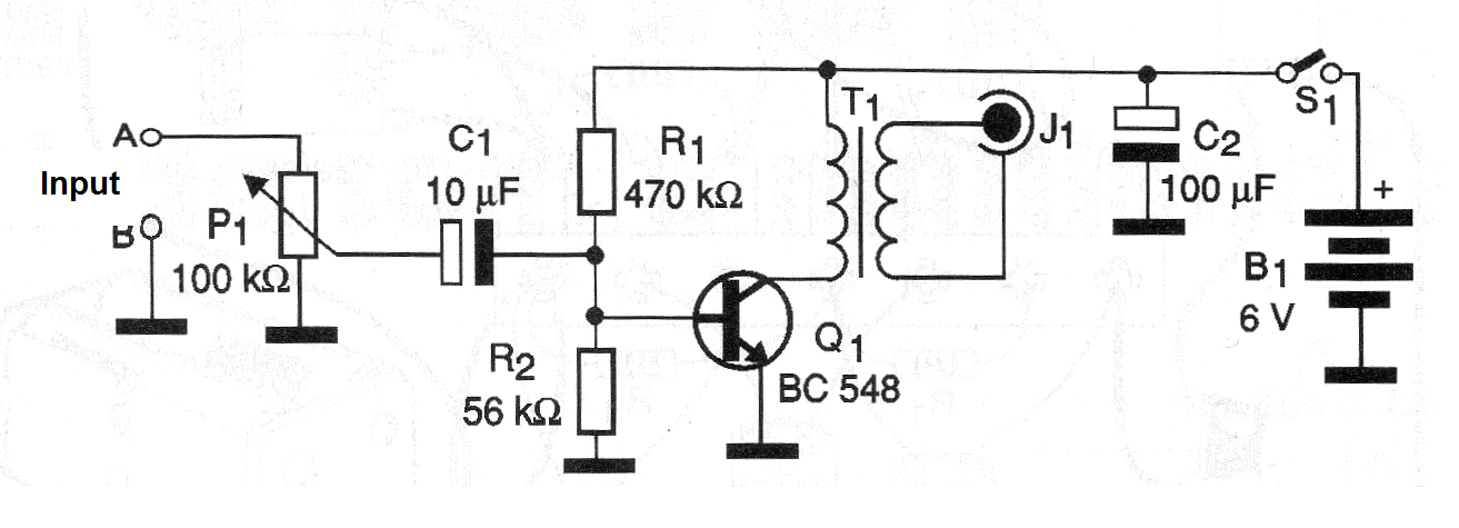
As the circuit uses few elements and is powered by ordinary batteries, it fits into a small plastic box that can be used together with the handset. In figure 1 we have the complete diagram of the booster amplifier for headphones.
The arrangement of the components based on a small terminal bridge is shown in figure 2.
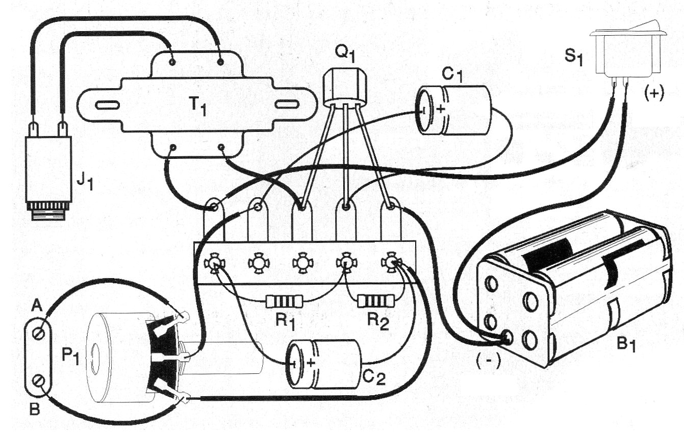
The transformer is the only somewhat critical component of the assembly because it is of a type that is no longer easily found in stores and therefore must be taken advantage of an old transistorized radio or other similar device such as cassette recorders, intercoms, etc.
It is an output transformer with a primary impedance between 200 and 2,000 ohms and a secondary impedance of 8 ohms or more.
In the latter case a small power transformer with 110 V or 220 V primary power supply and having a secondary from 4 to 12 V for a current between 50 and 250 mA can be used. These transformers have high impedance on the primary 110 V or 220 V and low impedance on the low voltage winding, exactly as we need for this application.
The low voltage winding is connected to the handset and the high voltage winding is connected to the transistor. The resistors are 1/8 W or larger and the electrolytes for 6 V or more working voltage. The potentiometer is common and may include the switch that turns the appliance on and off. The transistor supports equivalents such as the BC547, BC549 or any NPN of general use.
For batteries we need a suitable holder. Signal input can be done by means of two alligator clips, or a jack. We suggest the use of two short wires for ease of use.
If it is to be used in a specific application you can employ a plug according to the output jack of this application.
To try out the handset booster, simply turn on your power and tap your fingers in the doorway, fully opening its volume. A slight snore should be heard on the handset. This snore is of the alternating current of the network of energy captured by your body.
To use the unit, simply apply the signal to the input jacks and adjust the gain to P1 so that the best amplification is without distortion.
This circuit also works as a good follower of audio signals in the search for defects in audio equipment and small radios.
If a stereo handset is used the jack must be connected as shown in figure 3.
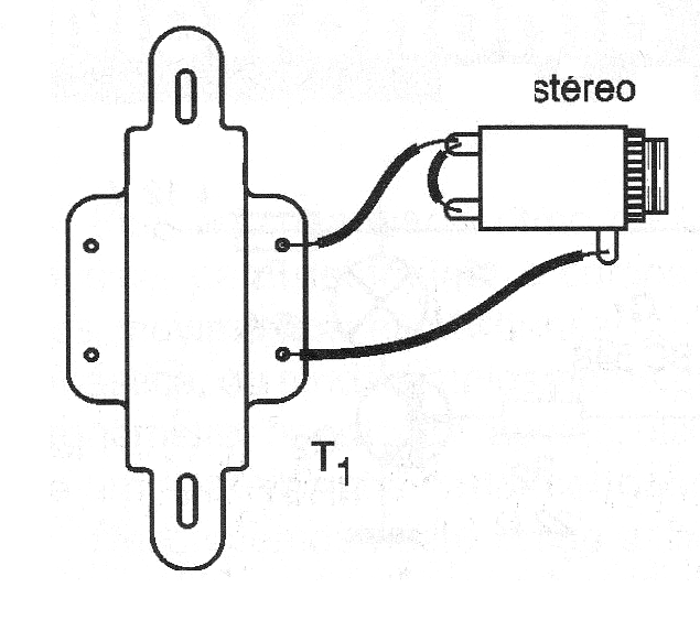
If the reader prefers, for a stereo headset can mount two amplifier channels, instead of just one.
MATERIAL LIST
Semiconductors:
Q1 - BC548 or equivalent - general purpose NPN transistor
Resistors: (1/8 W, 5%)
R1 - 470 k ohms - yellow, violet, yellow
R2 - 56 k ohms - green, blue, orange
P1 - 100 k ohms - potentiometer
Capacitors:
C1 - 10 uF / 6 V - electrolytic
C2 - 100 uF / 6 V - electrolytic
Miscellaneous:
T1 - Transformer - see text
S1 - Single switch
B1 - 6 V - 4 small batteries
J1 - jack according to the phone used
Terminal strip, battery holder, mounting box, alligator jaws, potentiometer knob, wires, solder, etc.


