
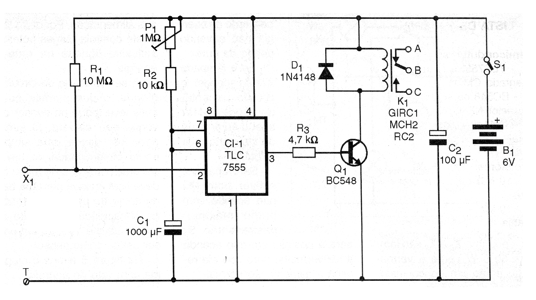
One touch on sensor element X1 and the relay closes its contacts thus remaining for a time interval determined by the setting of P1.
Motors and miscellaneous devices like solenoids and electromagnets can be triggered in robotics and mechatronics projects.
We can also use this circuit in alarms, alarm deactivation systems, door opening or in the timing of lamps.
The resting current of the circuit is very low, which allows its power with common batteries.
The relay, on the other hand, can control powerful loads, even connected in the power grid.
The sensitivity of the circuit is great, allowing the slightest touch on the sensor to trigger.
The sensor can be from a single bare end of a wire to a metal plate that must be insulated by a plastic or wooden support base.
A printed circuit board up to 15 x 15 cm can be used as a sensor.
In figure 1 we have the complete diagram of the apparatus.
The arrangement of the components on a printed circuit board is shown in figure 2.
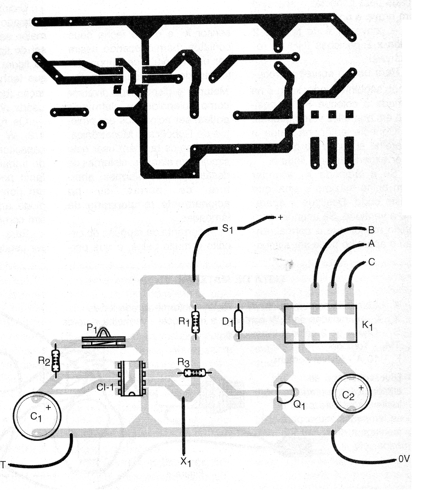
The integrated circuit must be installed in a DIL socket for extra safety.
The relay can be either of the type with the base provided in the figure as equivalent since they have supply voltage (coil) according to the one used in the design.
The resistors are all 1/8 watt or larger and the capacitors must have working voltages of 6 V or more.
P1 can either be a trimpot or a common potentiometer.
The diode supports equivalent as does the transistor.
4 batteries or power supply can be used for the power supply.
The operating test is simple: switch on the device and set P1 to a minimum time (less resistance).
By touching X1 and T at the same time with your fingers the relay should close its contacts thus remaining for a few seconds.
Then the relay disarms and the circuit can be triggered again with the same procedure.
To use the circuit with maximum sensitivity connect the T (ground) point to any point that has contact with the ground, such as a door or window metal window or even a metal faucet.
If the instability is checked, reduce the value of R1.
Then set P1 to the desired trip time and connect the relay contacts to the device to be controlled.
PS: The circuit also functions as the CMOS version of the 555 integrated circuit without any changes.
Parts List
Semiconductors:
CI-1 - 555 - integrated circuit, timer
Q1 - BC548 or equivalent - general purpose NPN transistor
D1 - 1N4148 - general purpose diode
Resistors: (1/8 W, 5%)
R1 - 10 M ohms - brown, black, blue
R2 - 10 k ohms - brown, black, orange
R3 - 4.7 k ohms - yellow, violet, red
P1 - 1 M ohms - trimpot or potentiometer
Capacitors:
C1 - 1000 uF / 6 V - electrolytic
C2 - 100 uF / 6 V - electrolytic
Miscellaneous:
K1 - General Purpose 6 V Relay
S1 - Single switch
B1 - 6 V - 4 common batteries
Printed circuit board, mounting box, battery holder, integrated socket, wires, solder, etc.


